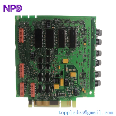
Description
- Model Number: CI534V02
- Material / P/N Code: 3BSE010700R1
- Brand: ABB (Asea Brown Boveri / Sweden)
- Series: Advant OCS / Advant Fieldbus 100 (AF100) / AC400 Controller Family
- Core Function: Serves as a high-speed communication interface card that connects an Advant Controller (like the AC410 or AC450) directly to the AF100 network, allowing real-time data exchange between processing stations.
- Condition: Brand New Surplus / Fully Verified Clean Stock (Sealed anti-static packaging)
- Product Type: AF100 Fieldbus Communication Interface Module
- Key Specs: Dual twisted-pair modem connection support | Direct backplane subrack bus integration | Embedded network traffic status indicators
- Network Protocol: Advant Fieldbus 100 (AF100)
- Data Transfer Profile: Deterministic cyclic data transmission combined with event-driven background communication.
- Physical Interface Links: Supports connection to standard AF100 twisted-pair modems (such as CI570 or standard TC512/TC513 media adapters).
- Power Draw: Extracted directly from the host Advant subrack chassis frame rails.
- Chassis Capacity: Slotted vertical printed circuit board format; occupies one standard communications interface slot inside an AC400 rack.
- Isolation Protection: Complete galvanic isolation safeguards the main controller CPU backplane from external industrial fieldbus surges.
- Diagnostic Panel Array: Front-facing LED network indicator lights tracking module health, bus activity, and line faults.
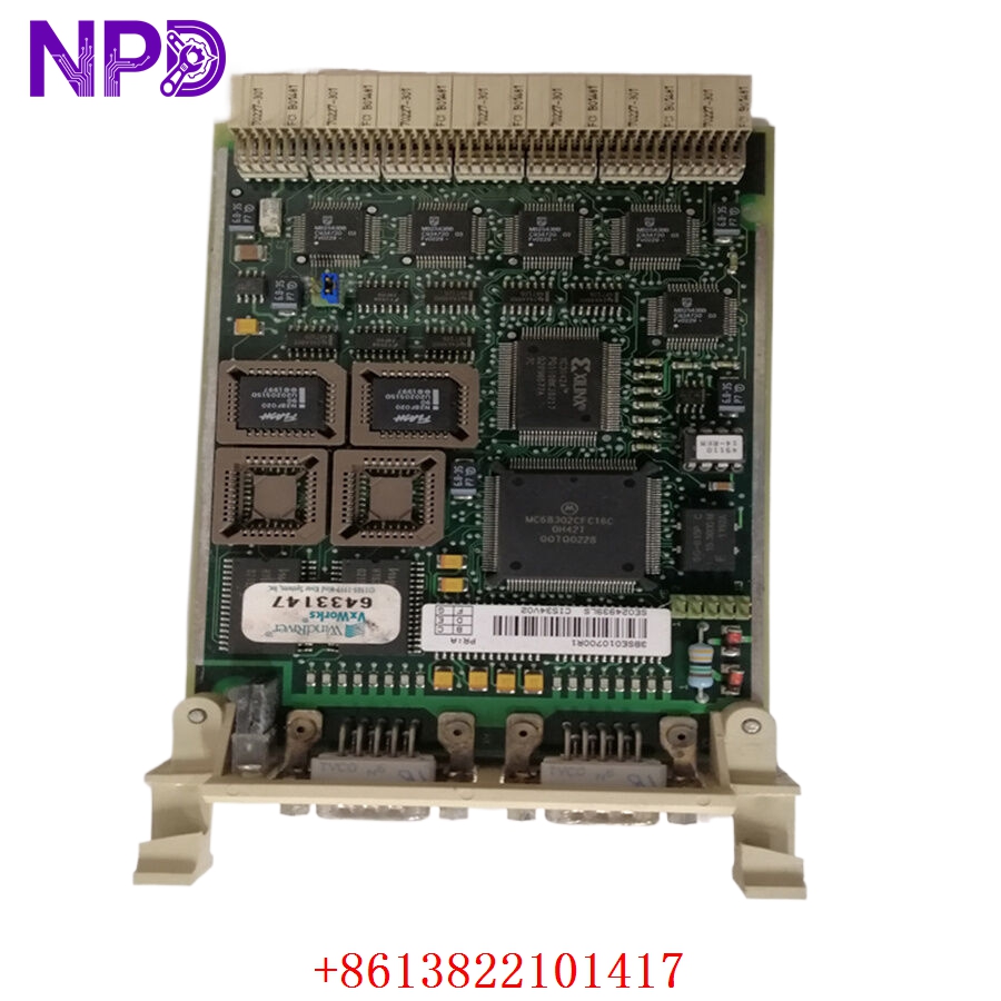
ABB CI534V02 3BSE010700R1
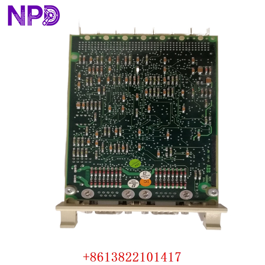
ABB CI534V02 3BSE010700R1
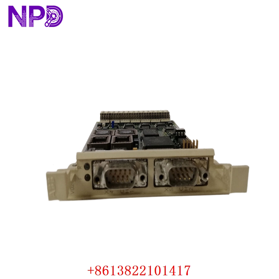
ABB CI534V02 3BSE010700R1
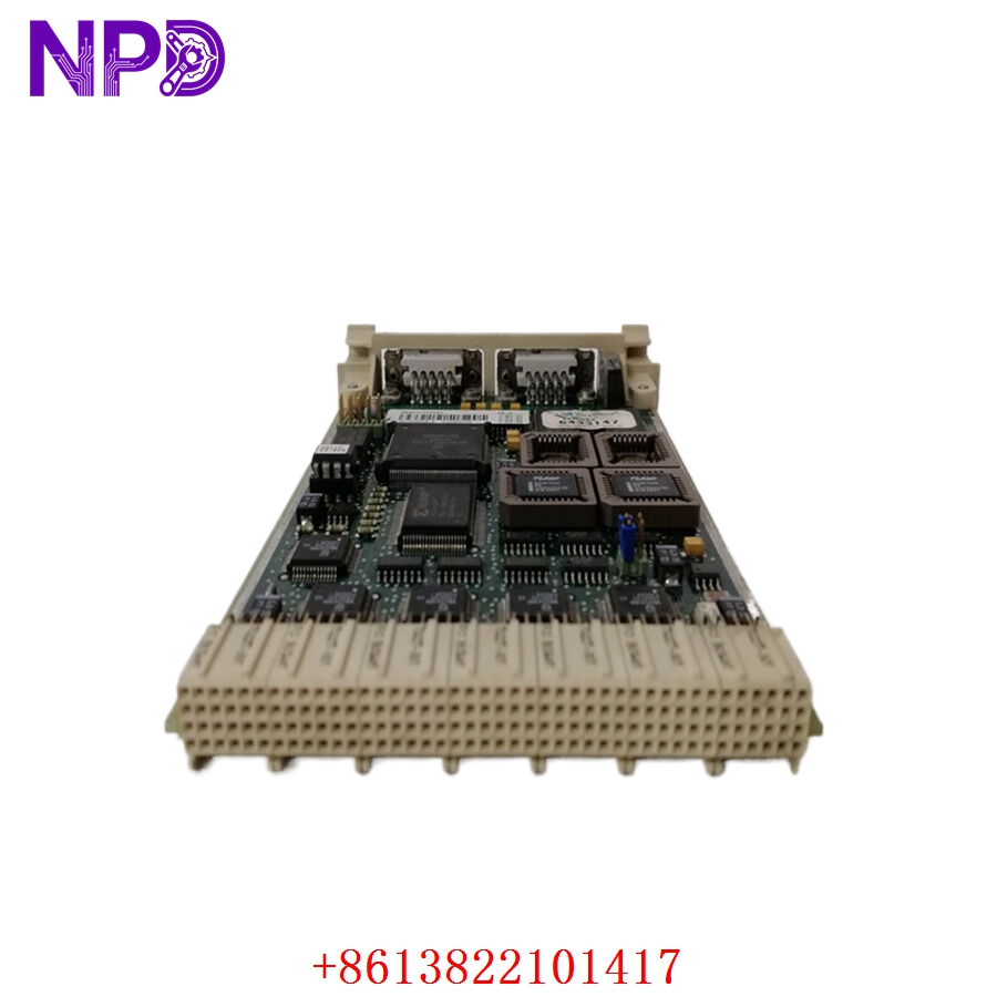
ABB CI534V02 3BSE010700R1
Application Scenarios & Engineering Pain Points
The CI534V02 3BSE010700R1 module is the central data pipeline for legacy ABB Advant Controller networks. Without this card, an AC410 or AC450 controller becomes isolated—unable to transmit process telemetry to the main operator HMIs (like Advant Station 500 or System 800xA) or sync critical safety interlocking data with adjacent controllers.
The primary engineering issue with this card centers around long-term thermal wear inside cramped control room racks and degradation of its line driver circuitry. Over time, the high-speed data cycling on the AF100 bus stresses the transceiver components, leading to intermittent packet drops. This appears as flickering communication alarms on the HMI. If the card fails completely, the whole controller disappears from the industrial network, forcing downstream subsystems into their default fail-safe states and halting production until a pre-configured replacement module can be installed.
Typical Field Deployments:
- Power Generation – Boiler Control Distributed Networks
Links multi-unit boiler controllers over an AF100 trunk line to coordinate master steam distribution and water feed pumps.
- Oil & Gas – Distillation Column Automation
Manages real-time data flow between localized loop controllers and safety instrumented systems across the processing facility.
- Pulp and Paper Mills – Multi-Section Drive Synchronization
Maintains high-speed deterministic control data lines across major drying and winding control nodes to prevent paper tears.
Case Study: The Blind Boiler Incident
- The Setup: A large district heating plant relied on an ABB AC450 controller grid connected via an AF100 loop using CI534V02 interface modules to track system pressure and temperature profiles.
- The Crisis: During an operational peak, an internal power surge damaged the communication driver chip on Node 3’s CI534V02 module. Node 3 went completely dark on the operator screens. The central HMI lost all telemetry for Boiler 3, triggering a system-wide “Net Node Timed Out” alarm. Because operator control was cut off, safety protocols forced an automated emergency trip of the burner system, halting steam delivery to the utility matrix. Every minute of down-time cost thousands in grid fines.
- The Fix: The instrument tech contacted our spare parts warehouse. We located a brand-new 3BSE010700R1 communication card in our stock, verified its bus logic on an active test rack, and dispatched the module via an emergency overnight courier.
- The Outcome: The card reached the site by 6:00 AM. The technician swapped out the damaged module, checked that the address jumper configuration matched the original layout, and locked it into the subrack slot. The controller established a network handshake with the master bus instantly, restoring full HMI graphics and allowing the operations team to safely restart the boiler before the morning load spike.
Standard Operating Procedure (SOP) Quality Transparency
Because communication network cards must stay rock-solid to avoid plant-wide dropouts, our electronics laboratory puts every CI534V02 module through a precise five-stage verification cycle before shipment:
[Pin & Trace Magnification Audit] ➔ [Subrack Integration Seating] ➔ [Deterministic Cyclic Data Run] ➔ [Bus Fault Emulation Test] ➔ [ESD Safe Pack] 1. Pin and Trace Magnification Audit
- Physical Micro-Audit: We examine the backplane connector fingers and surface traces under heavy magnification to check for microscopic cracks, solder fractures, or factory blemishes.
- Authenticity Check: Part number marks, board revisions, and tracking tags are checked against factory technical profiles to ensure the module is 100% genuine and unaltered.
2. Subrack Integration Seating
- Chassis Alignment: The vertical card is guided into an authentic AC400 series test chassis to ensure it slides cleanly along the guide rails and seats perfectly into the backplane connectors with zero mechanical resistance.
3. Deterministic Cyclic Data Run (Live Bench Test)
- Test Architecture: The module is linked to a functional master CPU card and hooked to an AF100 network loop with a matching modem interface.
- Data Log Loop: We push continuous cyclic data blocks across the interface at maximum bus speeds. We track packet delivery metrics to ensure zero data drops, checksum faults, or processing lag over extended testing cycles.
4. Bus Fault Emulation Test
- Redundancy & Error Verification: We deliberately break line connections on the network loop to verify that the card correctly detects the error, illuminates its front panel fault LEDs, and switches smoothly over to alternate data paths without locking up the CPU channel.
5. ESD Safe Packing and Dispatch
- Shielding Sealing: The verified card is packed into a heavy-duty, static-shielding bag inside an ESD-safe workspace.
- Cushioning Armor: Wrapped securely in multi-layer shock foam within rigid industrial shipping cartons to eliminate risk from transit impacts.
- Certification: Every unit is tagged with a physical QC Passed certificate noting the formal inspection date.
Technical Pitfall Mitigation Guide
When setting up or replacing a CI534V02 communication card, follow these essential field steps to ensure a smooth system installation.
1. Hardware Address Jumper Positioning
- The Risk: Advant Fieldbus cards rely on physical onboard jumpers or DIP switches to define their network node address and data rate configuration. If you slide a fresh, factory-default card into your rack without matching these hardware settings, the network will experience an address conflict or refuse to link up entirely.
- The Fix: Before placing the new module into the subrack, place it side-by-side with the old failed unit. Carefully mirror every jumper cap position and DIP switch toggle onto the replacement card to ensure it inherits the correct network identity.
2. Backplane Power Precaution
- The Risk: While some industrial systems allow hot-swapping fieldbus modules, the AC400 backplane bus contains dense logic lines that can short out if a card is slid out crookedly while powered. This can crash the main running CPU or damage adjacent cards.
- ❗ Crucial Warning: Always isolate power to the target controller subrack chassis before extracting or inserting the communication card. This protects the sensitive logic pins from unexpected voltage arcs during the swap.
3. Fiber-Optic / Coaxial Cable Care
- The Risk: When reconnecting cables to your AF100 modems via the CI534V02 interface, crimping or sharply bending the network cables will alter line impedance, causing intermittent data reflections that degrade network stability.
- The Fix: Maintain a clean routing path for all network cables. Observe the minimum bend radius guidelines for your data lines, and ensure the coaxial or twisted-pair connectors lock firmly into place on the modem terminals.
Compatible Replacement Models
If you are reviewing platform spare parts lists or assessing long-term maintenance strategies, note these hardware cross-reference profiles:
| Original Model Number | Potential Alternative | Compatibility Level | Key Differences | Necessary Field Action | Cost Impact |
| CI534V02 (3BSE010700R1) | CI534V01 | ❌ Incompatible | Older hardware generation with distinct internal timing parameters and lower maximum data processing capacities. | Do not use in modern AC450 or high-speed AF100 configurations; it will cause bus synchronization mismatch faults. | Variable legacy surplus pricing profile. |
| CI534V02 (3BSE010700R1) | CI522A | ❌ Physical Footprint Incompatible | Compact module form factor intended for alternative controller series like the AC800M line. | Cannot be inserted into standard AC400 subrack chassis slots; requires an entirely different system architecture layout. | Variable based on platform architecture. |
| CI534V02 | ABB Industrial Ethernet Migration (System 800xA) | ❌ Total Retrofit Required | Next-generation digitized control framework utilizing modern high-speed ethernet networks to replace legacy AF100 links. | Requires a complete engineering upgrade of the legacy controller hardware, application code, and fieldbus networking arrays. | High capital project expenditure (>400%). |
Troubleshooting Quick Reference
Use this field diagnostic guide to check performance if an AF100 communication interface reports an error:
| Diagnostic Symptom | Root Cause Probability | Card Relevance | Field Verification Steps | Recommended Remediation |
| Fault LED is solid Red | Internal power regulator failure, or a critical processing chip fault on the board. | ✅ High | Power down the rack, reseat the card firmly in its slot, and power up again. Monitor if the error clears. | If the Fault LED remains a solid red after power cycling, the card’s internal logic components are compromised. Replace the module. |
| Traffic LED stays dark during active operations | Broken network link cable, unpowered modem, or incorrect node address settings. | ⚠️ Medium | Check status lights on the external AF100 modem (e.g., CI570). Verify network cables are attached and termination resistors are securely in place. | Reconnect loose communication cables or replace the faulty external modem. If the modem is healthy but the card fails to send or receive data, swap the card. |
| Intermittent “Node Offline” drops reported on HMI | Corroded backplane connector fingers, or a failing line driver circuit on the card. | ✅ High | Pull the card out and inspect the rear connector pads for dust or copper oxidation. Clean using electronics-safe solvent. | If the drops persist after cleaning the contacts and verifying that network cables are healthy, the card’s signal driver circuit is breaking down under thermal load. Swap the card. |
Need immediate engineering backup? If your plant is down and you cannot pinpoint the failure node, drop our technical support desk an email with photos of your current indicator lights and a copy of your panel’s wiring diagram. We will have an integration engineer respond within 2 hours.