Description
- Model/Type Designation: ABB CI535V30 (Alternative spelling: CI535 V30 / Revision V30)
- Product ID/Part Number: 3BSE022162R1
- Brand: ABB (Asea Brown Boveri)
- System Control Architecture: Advant OCS / Advant Master (AC410 / AC450 Controller Subracks)
- Core Function: High-speed Advant Fieldbus 100 (AF100) communication interface module. It acts as the dedicated intelligent gateway matching the master controller’s internal backplane bus to the twin-axial or fiber-optic AF100 plant network loop, managing synchronous deterministic data transmission across the process control network.
- Operating Input Voltage: Derived directly via the controller subrack backplane (+5 V DC and +24 V DC rails)
- Power Dissipation: 6.5 W nominal processing load limits
- Network Protocol: Advant Fieldbus 100 (AF100) — Master/Slave deterministic token passing loop
- Data Transmission Rate: 1.5 Mbit/s high-speed fixed plant bus synchronization
- Interface Ports:
- Front Panel: Dual redundant attachment nodes for AF100 bus modems (e.g., connection to CI522A or TC512/TC513 media converters)
- Status Indicators: Specialized processing LED matrix arrays tracking Unit OK, Run, Traffic, and Line Fault codes
- Maximum Node Capacity: Connects the controller to a network loop supporting up to 80 active station nodes
- Isolation Boundary: 1,500 V AC continuous optical isolation protective barrier between backplane logic and network channels
- Operating Ambient Temperature: 0°C to +55°C continuous cabinet envelope limits
- Storage Temperature Window: -40°C to +85°C structural environment limits
- Relative Humidity Tolerance: 5% to 95% relative humidity (RH, non-condensing tracking)
- Conformal Coating: Premium industrial PCB layout coating for protection against dust and corrosive gases
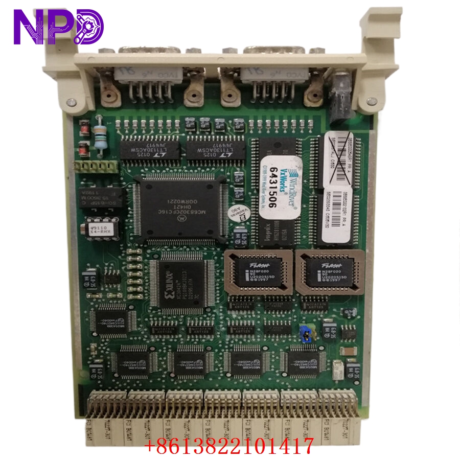
ABB CI535V30 3BSE022162R1
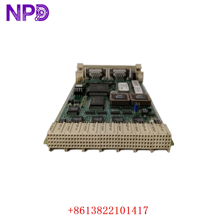
ABB CI535V30 3BSE022162R1
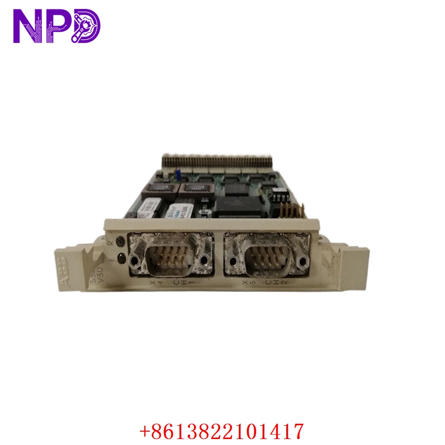
ABB CI535V30 3BSE022162R1
Installation & Configuration Guide
Pre-Installation Setup
⚠️ CRITICAL SAFETY WARNING:
- Coordinate a comprehensive control bypass window with the plant operations director before pulling a CI535V30 module. Removing this interface instantly drops the primary AF100 communication link for that controller rack, causing the central HMI consoles to lose telemetry and potentially triggering emergency shutdown interlocks.
- Ensure that the controller subrack processor has its backup battery enabled and functional to prevent memory loss when communication drops.
- Verify that the AF100 bus cables are correctly labeled as Line A and Line B to prevent cross-wiring during re-assembly.
- Required Tools & Gear:
- Grounded anti-static wrist strap clamped to the enclosure’s structural steel grounding bar.
- Standard 4.5 mm flathead insulated screwdriver for rack panel captive screws.
- Windows engineering notebook running ABB Ampl Control Configuration Software (AdvaBuild / Control Builder suite).
- Valid system network topology map (.wcf or project configuration backup file).
- Backup Procedures:
- Connect your laptop to the master controller configuration port and execute a complete database backup upload. Save the runtime parameters, node IDs, and network mapping layout safely offline.
- Document the physical positioning of the rotary address switches or dip-switch arrays on the legacy card surface.
Old Module Removal
- Isolate Network Traffic: Where possible, manually shift redundant processing tracks to the secondary backup controller node to minimize line disruptions.
- Disconnect Network Cabling: Disconnect the twin-axial or fiber media patch cables from the front interface ports. Secure the cables safely away from the slot path and apply dust caps to the connectors.
- Loosen Retaining Screws: Back out the captive mounting screws located at the top and bottom of the CI535V30 front faceplate using your flathead screwdriver.
- Eject and Withdraw: Pull the integrated extraction levers outward simultaneously to unseat the board’s high-density edge pins from the backplane receiver sockets. Slide the module straight forward out of the chassis track guides and place it on an ESD-safe workbench mat.
New Module Mounting and Configuration
- ESD Mitigation Check: Wear a grounded anti-static wrist strap while removing the new CI535V30 / 3BSE022162R1 card from its shielding packaging. Do not touch the rear gold-plated backplane connectors or open PCB components.
- Configure Hardware Address: Locate the rotary address switches or dip-switch banks on the new board’s surface. Set them to match the exact network station and node address of the old module to ensure the controller recognizes it on the AF100 network.
- Slide into Chassis Tracks: Align the top and bottom edges of the card housing with the plastic guide rails of the designated controller slot.
- Seat the Backplane Pins: Slide the module smoothly backward until the rear pins meet the backplane. Press the faceplate extraction handles firmly inward to lock the connectors into the backplane matrix.
- Secure Fasteners: Tighten the upper and lower captive faceplate retaining screws down snug (to roughly 0.6 N·m torque) to secure the module in place and establish a solid frame ground connection.
- Reconnect Network Cables: Reattach the AF100 network line connectors back into their matching front panel ports, checking that the Line A and Line B connections align correctly with your labels.
Post-Installation Verification Checklist
- [ ] Confirm that the rotary node address switches match the original card configuration exactly.
- [ ] Verify that all faceplate retaining screws are tightened down snug to establish a solid frame ground.
- [ ] Ensure that both network lines (Line A/Line B) are securely connected to their designated interface ports.
- [ ] Check that adjacent processor or interface modules inside the subrack were not disturbed or loosened.
Network Power-Up & Commissioning Run
- If the subrack power supply was turned off, re-engage the primary power circuit breaker. If the rack is live, the card will initialize immediately upon insertion.
- Monitor the diagnostic status indicators on the CI535V30 faceplate immediately:
- Unit OK (Green): Steady illumination indicates that the internal core processors passed self-test diagnostics.
- Run (Green): Illuminates steady when the card is executing its communication tasks and interacting properly with the backplane bus.
- Traffic (Flashing Green): Rapid flashing tracks live data packet transmission across the AF100 fieldbus loop.
- Line Fault (Red/Amber): Illuminates if the card detects a missing network connection, a loose cable, or an impedance mismatch on either Line A or Line B.
- Open your engineering workstation and access the AdvaBuild diagnostics tool tree. Verify that the hardware status icon for the target communication slot changes to a healthy online state.
- Download the network configuration database down to the rack to initialize the node’s cyclic data tables. This action will clear any pending configuration errors or line faults.
- Perform an operational validation check: verify that live process values from the controller populate correctly on the central HMI display screens without data delays or communication timeouts.
- Once the network connection is stable, clear the historical system event logs to complete the commissioning process.
Customer Cases & Industry Applications
Case 1: Steel Mill Rolling Line Network Telemetry Recovery
A large steel mill in northern China experienced a sudden communication failure on an Advant AC450 controller that managed a high-speed hot rolling line. The central control room lost all real-time telemetry from the section, and the main HMI screens displayed a persistent “AF100 Node Timeout” alert. This failure forced the engineering team to execute an emergency stop on the rolling line to prevent production tracking errors. Diagnostics identified that the primary CI535V30 AF100 fieldbus interface card had failed internally due to power surge degradation on the communication rail.
Because the rolling mill line was at a complete standstill, the mill faced high hourly downtime costs and needed an immediate replacement card. They contacted us to check our ready surplus stock. We pulled a brand-new surplus CI535V30 3BSE022162R1 module from our inventory, verified its data mapping circuits and transceiver paths on our specialized Advant OCS subrack test rig, and shipped it via priority air express that afternoon. The module arrived at the plant early the next morning. Technicians matched the rotary address settings, swapped the hardware, and restored full data communication to the HMI network within 18 hours of the initial breakdown.
Case 2: Petrochemical Refinery Desulfurization Unit Network Upgrade
During a scheduled maintenance turnaround at a petrochemical refinery, engineers identified intermittent data packet drops on an AF100 network loop that managed a critical desulfurization unit. The legacy communication interface module had been operating continuously for over a decade in a warm electrical room and was showing signs of components aging and erratic signaling.
[Legacy AF100 Card Degradation] ──> [Intermittent Packet Drops & Loss of Telemetry]
                                              │
              ┌───────────────────────────────┴───────────────────────────────┐
              ▼                                                               ▼
 [Option A: Complete DCS Migration]                               [Option B: Targeted Interface Card Renewal]
 • Cost: Very high capital expenditure (~$300,000+)               • Cost: ~85% savings compared to full migration path
 • Downtime: 2 weeks of engineering and logic recoding            • Downtime: Completed in under 30 minutes per rack
 • Execution Risk: High; requires a complete logic rewrite        • Execution Risk: Direct drop-in match; zero logic changes
The refinery’s automation team wanted a reliable solution that would not require replacing their existing, fully functional Advant controller processors or I/O racks. They chose to source two brand-new surplus CI535V30 3BSE022162R1 communication modules from our inventory. The maintenance crew completed the quick drop-in hardware swaps, set the rotary address switches to match the original node configuration, and re-engaged the network loop. This targeted replacement resolved the packet drop issues, stabilized data transmission to the control room, and extended the reliable service life of the refinery’s existing control infrastructure.
Frequently Asked Questions (FAQ)
Q1: What is the primary difference between the CI535V30 and older versions of the CI535 card?
A: The V30 designation represents a specific, updated hardware and firmware revision level for this AF100 interface module. The CI535V30 features optimized internal processing components, enhanced noise filtering on the communication paths, and an industrial-grade conformal coating layer. This coating helps protect the circuit board traces against moisture, dust, and corrosive gases (such as hydrogen sulfide) in harsh industrial environments, providing higher reliability compared to older non-coated variants.
Q2: Does the CI535V30 card require firmware flashing before installation in our subrack?
A: No, the module arrives with its core AF100 network operational code pre-loaded from the factory. It operates primarily as an intelligent hardware-driven communication manager. Once you set its onboard rotary address switches to match the slot and station assignment in your existing hardware profile, the card will automatically inherit its network configuration and cyclic data tables from the master controller upon power-up.
Q3: How do you verify the functionality of the AF100 bus interfaces before shipping?
A: Our quality assurance testing goes far beyond a simple visual check. We place every surplus module into an authentic ABB Advant Master subrack testing frame and connect it to an active AF100 simulation loop.
[Advant Test Rack] ──> [CI535V30 Module] <──> [AF100 Network Simulator]
                                                       │
                                                       ▼
                                      [24-Hour Continuous Cyclic Data Stress Test]
We subject the module to a continuous 24-hour cyclic data transfer stress test, sending and receiving packets to multiple simulated station nodes to verify full data throughput, stable timing, and signal integrity across both communication channels before the card leaves our facility.
Q4: Can the CI535V30 card handle both twin-axial copper and fiber-optic AF100 networks?
A: The CI535V30 module itself features standard interface ports that connect directly to ABB’s external bus modems or media converters. To integrate with a twin-axial copper network, it is typically paired with modems like the CI522A. For fiber-optic loops, it connects to specialized optical modems or media converters (such as the TC512 or TC513). This modular design allows the card to support either network medium depending on the external modems installed in your panel.
Q5: What do the different faceplate diagnostic LEDs indicate during a line fault?
A: The front panel diagnostic lights provide real-time troubleshooting feedback:
- Unit OK (Green): Steady green indicates the internal hardware passed its startup self-tests.
- Run (Green): Indicates the board is actively communicating with the controller backplane.
- Traffic (Flashing Green): Tracks active data packet transmission on the network loop.
- Line Fault (Red/Amber): Indicates a communication issue. A solid or flashing fault light typically means the card detects an open loop, a missing terminator, a disconnected cable on Line A or Line B, or an address conflict on the network.
Q6: What payment and shipping methods do you offer for urgent emergency plant shutdowns?
A: We accept international wire transfers (T/T), corporate credit cards, and standard letters of credit. For emergency repairs during an unplanned outage, send over a copy of your bank’s wire transfer confirmation slip. Our logistics team will immediately pull the part from our stock, complete our quality verification testing, and hand it off to an express air courier (like DHL or FedEx) to minimize your facility’s downtime.