Description
- Model Number: DSRF182AK02
- Material / P/N Code: 3BSE014078R1
- Brand: ABB (Asea Brown Boveri)
- Series: Advant OCS / S800 I/O
- Core Function: Serves as a high-performance serial communication interface/bus coupler, enabling seamless data exchange between the S800 remote I/O stations and the central controller (e.g., AC450 or AC800M).
- Condition: Brand New Surplus (Factory original packaging)
- Product Type: Serial Bus Interface / Communication Coupler
- Key Specs: High-speed serial data transmission, galvanic isolation, and ruggedized industrial housing.
- Communication Protocol: Dedicated S800 I/O bus integration protocol.
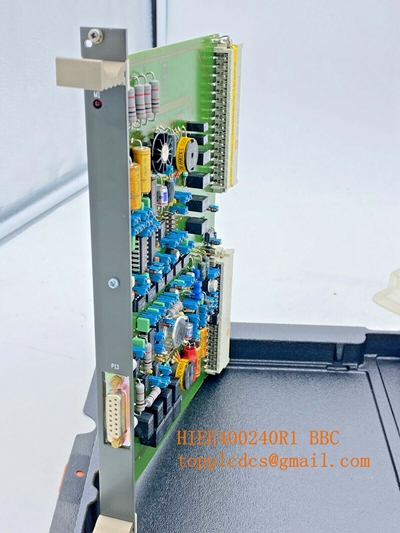
- Physical Interface: High-density D-sub or terminal-pin backplane connectors for secure attachment to the I/O mounting base.
- Isolation: Full galvanic isolation between the fieldbus and the internal logic processing circuitry.
- Environmental Ratings: Operates within standard industrial temperature ranges (-20°C to +70°C); moisture and vibration resistant.
- Indicator Matrix: LED status monitoring for “Run,” “Fault,” and “Comm” activity.
- Power Requirements: Standardized 24 V DC backplane supply.
ABB DSRF182AK02 3BSE014078R1
ABB DSRF182AK02 3BSE014078R1
ABB DSRF182AK02 3BSE014078R1
Engineering Pain Points & Troubleshooting
The DSRF182AK02 3BSE014078R1 is a critical component in distributed control systems. It is primarily used to bridge localized process data to the main controller. If this interface fails, the associated I/O rack “goes offline,” causing a loss of process visibility and potential system trips.
Common Failure Factors:
- Thermal Fatigue: Constant temperature cycling inside control cabinets can cause microscopic solder joint fractures on the communication chips.
- Grounding Loops: Improper shielding of serial cables can allow transient electrical noise to leak back into the module, resulting in intermittent data “glitches” or communication timeouts.
- Backplane Contamination: Dust or oxidation on the connector pins can lead to high-resistance contact points, manifesting as “module missing” alarms.
Standard Operating Procedure (SOP) Quality Transparency
To ensure operational integrity, our laboratory validates every module through a rigorous test sequence:
[Connector Pin Audit] ➔ [Power Supply Bench Test] ➔ [Data Packet Handshake Simulation] ➔ [Thermal Stress Stabilization] ➔ [ESD Vacuum Sealing] - Connector Pin Audit: High-magnification check for corrosion or bending on the backplane connector pins.
- Power Supply Bench Test: Verification of the 24 V DC conversion efficiency and idle current consumption.
- Data Packet Handshake Simulation: Testing communication throughput using a loopback signal generator to confirm the module processes bits at required millisecond intervals.
- Thermal Stress Stabilization: Running the module for 4 hours at elevated temperatures to ensure no logic drift occurs.
- ESD Vacuum Sealing: Packing in moisture-barrier bags with desiccant to prevent oxidation during storage.
Installation & Mitigation Tips
- Handling: Always use an anti-static wrist strap. Do not touch the gold-plated pins on the rear of the module.
- Shielding: Ensure that your serial communication cabling is correctly shielded and that the shield is grounded at the cabinet entry point only to avoid ground loops.
- Power Cycling: Before pulling the module from the base, always confirm the rack power is isolated. Replacing modules while the backplane is energized risks damaging adjacent modules due to inductive spikes.
Troubleshooting Quick Reference
| Symptom | Probable Cause | Action |
| Fault LED (Red) On | Internal logic failure or power input issue. | Power-cycle the rack; if the red light persists, replace the module. |
| Comm LED (Flashing/Dark) | Network cable fault or broken bus connection. | Check network termination resistors and cable continuity. |
| “Node Missing” Alarm | Address/configuration mismatch. | Verify hardware jumpers/switches match the original settings. |
Need immediate engineering assistance? If your process is down and you suspect this communication module, contact our technical support team with a photo of the module’s LEDs and your system’s error log; we can assist with remote diagnostics.