Description
- Model Number: NBIO-21CU
- Material / P/N Code: 3BSE017427R1
- Brand: ABB (Asea Brown Boveri)
- Series: S800 I/O / Advant OCS / MasterPiece Architecture
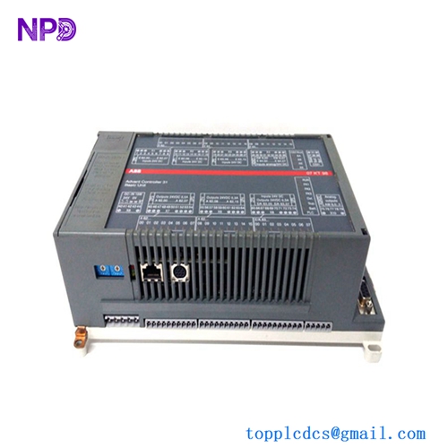
- Core Function: Acts as a compact, localized combination I/O base unit that interfaces both digital and analog field signals directly to a master controller via a fieldbus network.
- Condition: Brand New Surplus (Original factory-sealed box, non-refurbished)
- Product Type: Block I/O / Combination Terminal Base Unit
- Key Specs: 24 V DC Power Supply | Combined Analog Inputs/Outputs & Digital Inputs/Outputs | Integrated Fieldbus Connection Interface
- Rated Power Input: 24 V DC (Operational range: 19.2 V DC to 30 V DC)
- I/O Channel Matrix: Mixed digital and analog configuration layout optimized for compact remote terminal boxes.
- Analog Inputs: High-resolution current/voltage input loops (e.g., 0-20 mA, 4-20 mA)
- Analog Outputs: Configurable current/voltage loop driving circuits
- Digital Inputs/Outputs: 24 V DC rated discrete channels with high-speed response processing
- Isolation Barrier: Galvanic isolation between field channels, logic processing cores, and communication pathways to isolate noise.
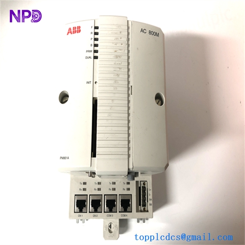
- Communication Interface: Integrated local cluster/fieldbus port linking directly to Advant field stations (e.g., AC 410, AC 450) or S800 I/O configurations.
- Mounting Profile: Standard DIN-rail attachment or direct panel backplate screw mounting.
- Protection Class: IP20
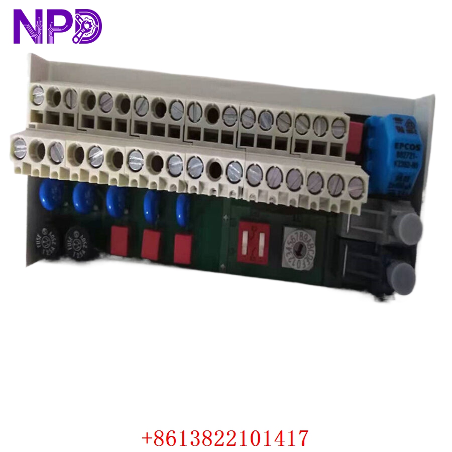
ABB 3BSE017427R1 NBIO-21CU
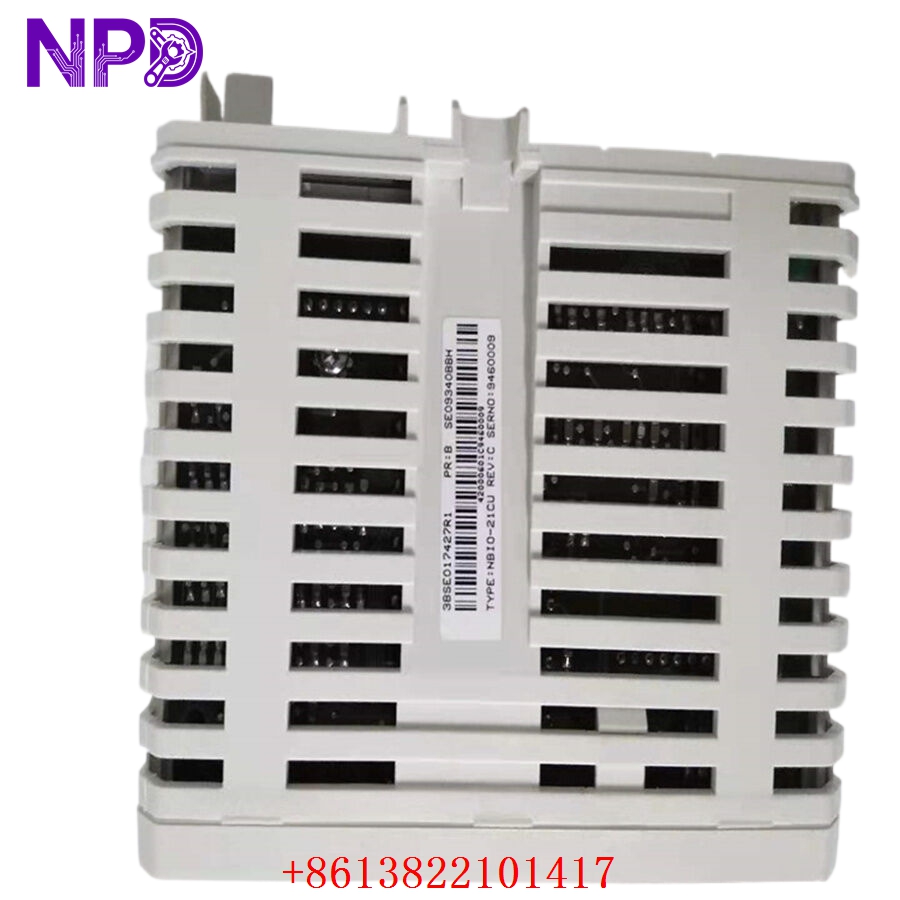
ABB 3BSE017427R1 NBIO-21CU
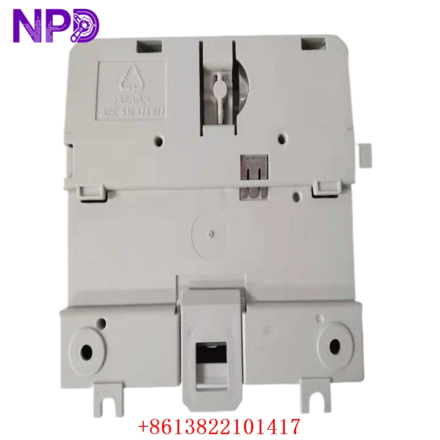
ABB 3BSE017427R1 NBIO-21CU
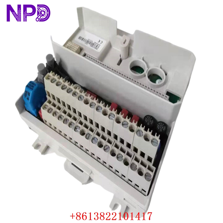
ABB 3BSE017427R1 NBIO-21CU
Application Scenarios & Engineering Pain Points
The NBIO-21CU 3BSE017427R1 is widely used in legacy ABB Advant OCS control topologies. Because it combines analog and digital I/O channels into a single physical unit, it is frequently installed in localized process nodes where running thick, multi-core home-run cables back to a central control room would be too expensive or logistically impossible.
The primary engineering headache with this module relates to its mixed signal paths. Because both high-speed discrete switching signals and sensitive analog measurement loops land on the exact same board chassis, any electrical ground shift or severe noise ingress can cause signal cross-talk. If moisture or corrosive industrial gasses compromise the terminal connections, analog readings will drift erratically, or the module will drop off the fieldbus entirely (throwing a “Node Missing” or “Module Position Error” on the central operator station). When an older NBIO-21CU node fails, it can bring down an entire subsystem (like a localized water filtration plant or oil-pumping outpost), making a drop-in replacement essential.
Typical Field Deployments:
- Chemical Plant Off-Site Facilities – Remote Tank Gauging
Gathers analog levels and high/low digital float switches from distributed storage tanks and routes the data back to an AC450 central controller.
- Water/Wastewater Treatment – Dosing Station Management
Monitors precise flow rates via analog inputs while simultaneously controlling discrete chemical dosing pumps using its onboard digital outputs.
- Pulp and Paper Mills – Auxiliary Roller Controls
Manages local hydraulic pressure values and solenoid valves on secondary tensioning equipment.
Case Study: The Lost Remote Pump Node
- The Setup: A large pulp mill in Southeast Asia used a series of distributed S800 / Advant networks to coordinate water intake lines from an onsite reservoir. A remote pumping shack relied on an NBIO-21CU module to monitor water pressure and actuate the main isolation valves.
- The Crisis: During an electrical storm, a nearby lightning strike induced a severe voltage surge in the underground field grounding grid. The transient energy bypassed the terminal surge arrestors and entered the NBIO-21CU’s communication transceiver chip. The module died instantly, taking the remote station completely offline. The main control system lost all pressure telemetry and immediately locked out the supply pumps to prevent line rupture. This halted fresh process water delivery to the paper line, threatening a complete plant shutdown within a few hours.
- The Fix: The instrument supervisor contacted our team. We located a brand-new 3BSE017427R1 base module in our climate-controlled warehouse, verified its power consumption profiles on a test backplane, and rushed the package out on an express air freight shipment.
- The Outcome: The module arrived at the plant the next morning. The technician disconnected the terminal blocks, swapped the failed module on the DIN rail, reconnected the field lines, and powered up the unit. The master controller automatically picked up the module node address, cleared the field bus fault, and safely restarted the intake pump lines within 30 minutes of delivery.
Standard Operating Procedure (SOP) Quality Transparency
Because distributed control system infrastructure demands absolute continuity, our engineering workshop runs every NBIO-21CU through a comprehensive testing matrix before packaging:
[Visual Trace & Terminal Audit] ➔ [Power Bus Current Verification] ➔ [Analog / Digital Channel Loop Tests] ➔ [Fieldbus Network Handshake] ➔ [ESD Safe Sealing] 1. Visual Trace and Terminal Audit
- Physical Inspection: We check the terminal screw blocks and rear interface connectors under high magnification for cracked solder points, manufacturing defects, or pin misalignments.
- Authenticity Mapping: Laser-etched barcodes, firmware labels, and model markings are verified against ABB’s factory specifications to guarantee genuine, original parts.
2. Power Bus Current Verification
- Baseline Energizing: The module is supplied with a regulated 24 V DC power line. The current draw is continuously logged to ensure the module’s internal power converters operate smoothly without generating excess heat.
3. Analog and Digital Channel Loop Tests
- Simulation Mapping: We inject precise analog signals (4-20 mA) into the inputs and check that the digital values are scaled accurately. We toggle the discrete input/output pins under full load to confirm that every internal optocoupler switches cleanly.
4. Fieldbus Network Handshake
- Communication Trace: The unit is linked into a standard test bus topology to verify that it communicates properly with the master processor, confirming zero data packet drops or transmission lag.
5. ESD Safe Sealing and Dispatch
- Shielded Protection: The verified card is placed inside an anti-static moisture-barrier pouch alongside fresh desiccant packs.
- Rigid Armor: Packaged inside dense, shock-absorbent foam enclosures inside a heavy-duty carton box to ensure it survives transit vibrations.
Technical Pitfall Mitigation Guide
When upgrading or replacing an NBIO-21CU block module, please review these key technical reminders to prevent startup issues.
1. Address Jumper and Rotary Switch Coordination
- The Risk: S800 block I/O units rely on physical rotary dials or hardware jumper positions to establish their network node identity. If you slide a new, factory-default card into place without copying the address switch layout of the old module, the master controller will not recognize the node, resulting in a continuous communication fault.
- The Fix: Before mounting the replacement unit, look at the rotary switch dials or jumper pins on the side of the original failed module. Set the dials on the new NBIO-21CU to the exact same positions.
2. Proper Field Shielding Terminations
- The Risk: Because analog and digital lines terminate in close proximity on this compact block, inadequate shield grounding will introduce noise into your analog telemetry.
- ❗ Important Note: Ensure all analog signal cable shields are grounded at exactly one reference point (typically inside the main terminal cabinet). Do not ground both ends of a shield wire, as this can create a ground loop that introduces erratic errors into your readings.
3. Hot-Swap Precaution
- The Risk: While some S800 modular networks support hot-swapping under power, pulling a combination fieldbus block I/O unit like the NBIO-21CU while energized can cause an inductive spike across the remaining network legs, momentarily knocking down adjacent nodes.
- The Fix: Always isolate the local 24 V DC power feed breaker to the specific I/O block before disconnecting the terminal strips and replacing the hardware unit.
Compatible Replacement Models
If you are updating your spare parts inventory or assessing legacy migration strategies, review these reference alternatives:
| Original Model | Potential Alternative | Compatibility Level | Key Differences | Necessary Field Action | Cost Impact |
| NBIO-21CU (3BSE017427R1) | NBIO-21 (Older Suffix Variants) | ⚠️ Software Compatible | May contain older firmware revisions or feature slightly different terminal screw clamp materials. | Verify that your master controller’s hardware definitions accept older firmware revisions without forcing a system update. | Slightly lower cost on surplus markets. |
| NBIO-21CU | S800 Modular Components (AI810 + DO810 + TU810) | ❌ Physical Footprint Incompatible | Splits the functions across separate, dedicated analog and digital cards mounted on standard backplane slots. | Requires re-wiring the terminal box, modifying cabinet dimensions, and altering the controller’s I/O configuration tree. | Higher component and engineering cost layout (+180%). |
| NBIO-21CU | ABB Select I/O Platform | ❌ Total Retrofit Required | Next-generation digitized single-channel architecture utilizing advanced ethernet communication pathways. | Requires completely upgrading the legacy Advant controller to the System 800xA platform. | High capital project expenditure (>400%). |
Troubleshooting Quick Reference
Use this field matrix to isolate performance issues before pulling the module from the DIN rail:
| Diagnostic Symptom | Root Cause Probability | Card Relevance | Field Verification Steps | Recommended Remediation |
| Run LED is dark, Error LED is solid Red | Internal power supply failure, or a critical chip fault on the board. | ✅ High | Check that incoming voltage across terminals measures a stable 24 V DC. | If input power is verified but the Error LED remains a solid red after power cycling, the internal processor chip is compromised. Replace the module. |
| All analog readings are locked at maximum value (e.g., 22 mA) | Loss of field return loop ground, or a blown input resistor trace. | ⚠️ Medium | Disconnect the field wires and attach a loop calibrator directly to an analog input channel. Inject a solid 12 mA signal. | If the system now reads the 12 mA properly, search for a broken wire or short in your field cables. If the loop input remains locked at full scale, the card’s input circuit is damaged. Swap it. |
| Traffic/Comms LED is dark or flashing erratically | Misconfigured node address switches, or a broken network cable link. | ⚠️ Medium | Verify that the hardware address dial numbers match your software configuration drawings exactly. Check network termination resistor switches. | Adjust the rotary dials to match the original layout. If the addressing is correct but communication fails to connect across multiple racks, check for broken network cables or look for a malfunctioning master interface module. |
Need immediate engineering backup? If your plant is down and you cannot pinpoint the failure node, drop our technical support desk an email with photos of your current indicator lights and a copy of your panel’s wiring diagram. We will have an integration engineer respond within 2 hours.