Description
Product Description
The ABB REC670 Relion 670 Bay Control Intelligent Electronic Device (IED), part number 1MRK002814-AA, is designed for bay-level control, monitoring, protection, and automation in high-voltage and medium-voltage electrical substations. It provides control functions for circuit breakers, disconnectors, and earthing switches, together with electrical measurements, interlocking logic, event recording, and communication with station-level automation systems. The REC670 supports integration into substation architectures using IEC 61850 and other supported communication protocols, depending on the installed hardware and firmware configuration. Its modular design allows the selection of power supply, binary input/output, current and voltage measurement, and communication modules to meet specific project requirements. The device is suitable for substation modernization, protection and control panel maintenance, and replacement of compatible Relion 670 installations. Before commissioning, verify the complete ordering code, hardware configuration, firmware version, application logic, and communication settings.
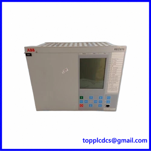
REC670 1MRK002814-AA
Product Datasheet – 10 Key Parameters
- Brand: ABB
- Model: REC670
- Part Number: 1MRK002814-AA
- Series: Relion 670
- Product Name: Bay Control Intelligent Electronic Device (IED)
- Manufacturer: ABB
- Country of Origin: Sweden (verify individual unit nameplate)
- Product Status: Legacy configuration; verify availability and revision
- Dimensions: Depends on case size; 6U rack-mounted design
- Power Requirements: Auxiliary supply configuration must be checked; REC670 versions support 24–60 V DC or 90–250 V DC, depending on installed power supply module
Additional Technical Specifications
- Application: Substation bay control and automation
- Control Functions: Circuit breaker, disconnector, and earthing switch control
- Current Inputs: 1 A or 5 A CT inputs, depending on configuration
- Voltage Inputs: 110 V nominal secondary voltage configuration
- Rated Frequency: 50/60 Hz
- Communication: IEC 61850, IEC 60870-5-103, Modbus, and DNP3, depending on hardware and firmware
- Ethernet: Electrical or optical interfaces, depending on installed communication modules
- Binary Inputs: Configuration-dependent
- Binary Outputs: Configuration-dependent
- Mounting: 19-inch rack, flush mounting, or wall mounting options
- Front Protection: IP40; IP54 with sealing strip
- Rear Protection: Depends on terminal arrangement
- Operating Temperature: Verify the applicable product revision and installation specification
⚙️ Operating Instructions and Usage
1. Installation and Preparation
- Verify the complete ordering code 1MRK002814-AA.
- Compare the replacement IED with the original unit’s nameplate and hardware configuration.
- Confirm the installed power supply module and rated auxiliary voltage.
- Check CT and VT input ratings and wiring polarity.
- Verify binary input and output module assignments.
- Inspect the communication interfaces and fiber-optic or Ethernet connections.
- Check circuit breaker, disconnector, and earthing switch feedback wiring.
- Confirm grounding, terminal tightness, and panel ventilation.
- Back up the existing application configuration before replacement.
2. Power-On Sequence
- Confirm that the substation bay is in an approved maintenance or commissioning condition.
- Ensure circuit breaker and isolator operations are controlled by the authorized switching procedure.
- Verify the auxiliary supply voltage and polarity.
- Check all CT and VT secondary connections.
- Energize the REC670 auxiliary power supply.
- Allow the IED to complete its startup and self-supervision checks.
- Check the front-panel display and diagnostic indicators.
- Verify communication with the station control system.
- Confirm binary input and output status.
- Check active alarms and protection availability before enabling operational control.
3. Normal Operating Procedure – Step by Step
- Check the REC670 operating status.
- Verify communication with the station-level control system.
- Review active alarms and event records.
- Check voltage, current, frequency, and other available measurements.
- Confirm circuit breaker and disconnector position indications.
- Verify interlocking conditions before issuing switching commands.
- Select the authorized local or remote control mode.
- Execute breaker or disconnector commands according to the approved switching procedure.
- Confirm that the actual equipment position matches the command.
- Monitor protection indications, event records, and communication status during operation.
4. Shutdown Sequence
- Transfer bay control functions to an approved alternative arrangement if required.
- Confirm that no switching operation is in progress.
- Follow the substation switching and isolation procedure.
- Ensure CT secondary circuits remain safely connected or shorted as required.
- Save relevant event records and configuration data.
- Isolate the auxiliary supply according to the approved maintenance procedure.
- Verify that the IED is de-energized before removing it.
- Disconnect communication and signal wiring carefully.
- Label all connections before replacement or maintenance.
5. Parameter Setting and Modification
- Use ABB PCM600 engineering software with compatible connectivity packages and firmware.
- Back up the original REC670 configuration before making changes.
- Verify the IED hardware configuration and application version.
- Configure CT and VT ratios and measurement scaling.
- Review circuit breaker and disconnector control logic.
- Configure binary input and output assignments.
- Check interlocking logic and switching permissions.
- Configure protection functions and operating thresholds according to the approved protection coordination study.
- Set IEC 61850 communication parameters, including station configuration, data mapping, and GOOSE subscriptions where applicable.
- Verify time synchronization and event recording settings.
- Download approved configurations and perform functional tests before returning the IED to service.
6. Safety and Maintenance Precautions
- Only qualified protection and control engineers should modify IED settings.
- Never open a live CT secondary circuit.
- Verify VT isolation and grounding before maintenance.
- Do not bypass circuit breaker interlocks or protection functions.
- Never issue switching commands without authorization.
- Use ESD protection when handling electronic modules.
- Maintain backups of PCM600 projects and approved configuration files.
- Check communication alarms, terminal connections, and diagnostic logs periodically.
- Perform secondary injection and functional testing after replacement.
🔧 Recommended 15 Other ABB Models
- ABB REL670 – Line Distance Protection IED
- ABB RED670 – Line Differential Protection IED
- ABB REG670 – Generator Protection IED
- ABB RET670 – Transformer Protection IED
- ABB REB670 – Busbar Protection IED
- ABB REC650 – Bay Control IED
- ABB REC615 – Bay Control and Protection IED
- ABB REF615 – Feeder Protection and Control IED
- ABB REF620 – Feeder Protection IED
- ABB REF630 – Feeder Protection and Control IED
- ABB RET615 – Transformer Protection IED
- ABB RET620 – Transformer Protection IED
- ABB RET630 – Transformer Protection and Control IED
- ABB REU615 – Voltage Protection and Control IED
- ABB REM615 – Motor Protection and Control IED
Compatibility Note: REC670 ordering code 1MRK002814-AA must be matched against the original unit’s complete hardware configuration. Do not assume that another REC670 ordering suffix has identical power supply, I/O, communication, or application functions.