Description
Product Description
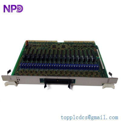
The HIMA F6217 is an eight-channel safety-related analog input module designed for acquiring process measurement signals in HIMA H41q and H51q safety control systems. It accepts 0/4–20 mA current signals and 0–5/10 V voltage signals, with safety isolation and 12-bit analog-to-digital conversion. The module is designed for safety instrumented applications requiring reliable acquisition of pressure, temperature, flow, and level transmitter signals. It has a 50 ms measurement update time and a safety response time of less than 450 ms. Tested for AK6/SIL3 applications, the F6217 provides an interface between field instrumentation and the HIMA safety controller. For system integrators, commissioning requires verification of the input signal range, current-channel shunt resistor, field wiring, channel allocation, controller configuration, and safety application validation. The exact hardware revision and system compatibility must be checked before replacement.
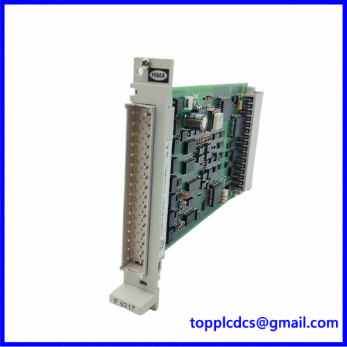
F6217
Technical Specifications
- Brand: HIMA
- Model: F6217 / F 6217
- Series: H41q / H51q HIQuad Safety System
- Product Name: 8-Channel Safety-Related Analog Input Module
- Product Type: Safety Analog Input Module
- Number of Channels: 8 analog input channels
- Current Input: 0/4–20 mA
- Voltage Input: 0–5 V / 0–10 V nominal signal ranges; verify the applicable input configuration
- Measurement Voltage Range: 0–5.5 V
- Maximum Input Voltage: 7.5 V
- Measurement Current Range: 0–22 mA through an external shunt resistor
- Maximum Input Current: 30 mA
- Current Shunt: 250 Ω, 0.05%, 0.25 W; HIMA part number 00 0710251
- Resolution: 12 bit
- Measurement Update Time: 50 ms
- Safety Time: Less than 450 ms
- Input Resistance: 100 kΩ
- Input Filter Time Constant: Approximately 10 ms
- Basic Error: 0.1% at 25°C
- Operating Error: 0.3% from 0°C to +60°C
- Safety-Related Error Limit: 1%
- Electrical Strength: 200 V against ground
- Safety Classification: Tested for AK6 / SIL 3 applications
- Backplane Power: 5 V DC, 80 mA
- Auxiliary Power: 24 V DC, 50 mA
- Space Requirement: 4 TE
- Dimensions: Approximately 210 × 128 × 21 mm
- Weight: Approximately 0.14 kg
- Place of Manufacture: Germany, according to HIMA product references
- Country of Origin: Germany, subject to individual unit nameplate confirmation
- Product Status: Seller-stated condition; confirm whether the offered card is new, surplus, or pre-owned
- Discontinued: Legacy product; confirm current manufacturer support and spare-parts availability
Operating Procedures
1. Preparation
- Confirm the module identification label reads F6217.
- Check the hardware revision and compatibility with the installed HIMA H41q or H51q system.
- Review the safety system configuration and approved I/O channel allocation.
- Identify the field transmitter type and signal range for each channel.
- Verify the required 250 Ω shunt resistor for current-input configuration.
- Inspect the module, front connector, PCB, and backplane contacts.
2. Installation
- Place the safety system in the approved maintenance state.
- Isolate the relevant power sources according to the site’s safety procedure.
- Install the module in the designated HIMA rack position.
- Confirm the module is correctly seated and mechanically secured.
- Check the front connector and field wiring arrangement.
- Ensure the rack and cabinet grounding meet the system requirements.
3. Electrical Connection
- Connect field transmitters according to the HIMA F6217 wiring diagram.
- Verify polarity and terminal assignments for every channel.
- Use the specified shunt resistor for current-input operation.
- Confirm voltage and current signals remain within the permitted input limits.
- Check cable shielding and grounding.
- Verify the 5 V DC backplane supply and 24 V DC auxiliary supply requirements.
- Do not apply field signals before confirming the configured channel type.
4. Power-On
- Verify module seating, field wiring, and system power connections.
- Energize the system according to the approved startup procedure.
- Check module status and controller diagnostic information.
- Confirm that all configured channels are recognized.
- Investigate channel faults before returning the safety system to service.
5. Normal Operation
- Monitor analog input values in the HIMA engineering environment.
- Compare displayed values with field transmitter readings.
- Check for channel faults, signal out-of-range conditions, and wiring errors.
- Verify that process values are correctly scaled in the safety application.
- Record diagnostic events and abnormal signal behavior.
6. Configuration
- Use the approved HIMA ELOP II engineering environment and applicable system documentation.
- Configure the correct input type and measurement range for each channel.
- Verify channel allocation and controller I/O mapping.
- Check scaling, signal limits, and diagnostic behavior.
- Confirm that the safety application uses the correct channel assignments.
- Back up the existing configuration before changing any parameters.
- Complete the required proof tests and validation procedures before returning the system to operation.
7. Shutdown
- Place the process in the approved safe maintenance condition.
- Follow the site’s safety isolation and lockout/tagout procedure.
- Isolate the relevant system power before removing the module.
- Label field wiring before disconnection.
- Protect the removed module from electrostatic discharge.
- Record the module revision and rack position for maintenance traceability.
Daily Maintenance
- Review module and controller diagnostic messages.
- Monitor analog values for abnormal fluctuations or out-of-range readings.
- Compare selected process values with field instrument readings.
- Inspect field wiring and terminal connections during scheduled maintenance.
- Check for moisture, dust, corrosion, and overheating inside the control cabinet.
- Verify that the module remains securely installed.
- Maintain backups of approved safety application configurations.
- Record module revision, channel assignments, and maintenance history.
- Perform periodic proof testing according to the site’s safety lifecycle procedures.
- Do not modify safety-related parameters without an approved management-of-change process.
Troubleshooting
1. Module is not recognized
- Check that the F6217 is installed in the correct rack position.
- Inspect the backplane and module contacts.
- Verify hardware revision compatibility.
- Review controller and system diagnostic messages.
2. Analog input reads zero
- Check field transmitter power and wiring.
- Verify signal polarity and terminal assignments.
- Confirm the correct current or voltage input configuration.
- Inspect the current shunt resistor where applicable.
3. Analog value is inaccurate
- Check the transmitter output and calibration.
- Verify the input signal range and engineering-unit scaling.
- Inspect the 250 Ω shunt resistor and its tolerance.
- Check field wiring resistance and grounding.
- Compare the measured signal with a calibrated reference instrument.
4. Channel reports an input fault
- Inspect the transmitter and field cable for open circuits or short circuits.
- Verify that the signal remains within the permitted input range.
- Check channel configuration and wiring.
- Review the controller’s diagnostic information.
5. Intermittent analog readings
- Inspect terminal connections and cable shielding.
- Check for electrical interference from nearby drive or power cables.
- Verify transmitter power stability.
- Review grounding and cable routing.
6. Safety system reports a module fault
- Record the diagnostic code and module revision.
- Check the system power supply and backplane condition.
- Follow the HIMA diagnostic and fault-recovery procedure.
- Do not bypass safety diagnostics or force channel values to clear a fault.
Safety Precautions
- Work on safety-related equipment must be performed by qualified functional-safety personnel.
- Follow the site’s approved permit-to-work and lockout/tagout procedures.
- Never remove or insert the module unless the system documentation explicitly permits the procedure.
- Verify field signal ranges and terminal assignments before wiring.
- Use the specified precision shunt resistor for current-input configuration.
- Do not exceed the module’s maximum input voltage or current.
- Do not bypass module diagnostics or safety interlocks.
- Any change to channel configuration, wiring, or safety logic requires appropriate review and validation.
- Confirm the exact hardware revision and system compatibility before replacement.
- Complete required proof testing before returning the safety instrumented function to service.
Product Keywords
HIMA F6217, HIMA F 6217, HIMA analog input module, 8-channel analog input, HIMA safety module, HIMA HIQuad, H41q, H51q, SIL 3 safety system, AK6 safety module, 4–20 mA input module, 0–10 V analog input, safety instrumented system, SIS spare parts, industrial safety automation.
For industrial automation products and spare parts, visit https://www.newplcdcs.com.
Related HIMA Models and Product Families
The following are related HIMA safety-system modules and product families for sourcing research. They are not confirmed direct replacements for F6217.
- HIMA F6212 – Analog input module family
- HIMA F6213 – Analog input module family
- HIMA F6214 – Analog input module family
- HIMA F6215 – Analog input module family
- HIMA F6216 – Analog input module family
- HIMA F6220 – 8-channel analog input and temperature module
- HIMA F6221 – Analog input module
- HIMA F3221 – Digital input module family
- HIMA F3236 – Digital input module family
- HIMA F3330 – Digital output module family
- HIMA F3331 – Digital output module family
- HIMA F4204 – Analog output module family
- HIMA F7130 – Power supply module family
- HIMA H41q – Safety controller system family
- HIMA H51q – Safety controller system family