Description
Product Description
The Bosch Rexroth Indramat DKC11.3-040-7-FW, part number R911279433, is an EcoDrive 03 digital servo drive controller designed for industrial motion-control applications. This version 3 controller belongs to the DKC11 series and has a 40 A current class with a 700 V DC-bus voltage category. It is intended for use with compatible servo motors and machine-control systems requiring controlled speed, torque, and position operation. The drive provides motor power connections, control-voltage connections, feedback and control interfaces, and provisions for a programming module. Its application depends on the correct firmware, motor data, feedback configuration, and machine-specific control wiring. For system integrators maintaining legacy CNC equipment, machine tools, and production machinery, the DKC11.3-040-7-FW can serve as a service replacement when the original hardware configuration and application requirements are verified. Confirm the firmware module, hardware index, motor compatibility, and electrical ratings before commissioning.
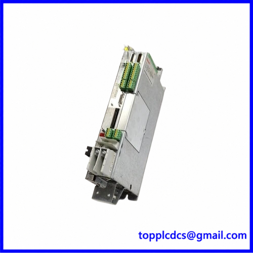
DKC11.3-040-7-FW
Technical Specifications
- Brand: Bosch Rexroth / Indramat
- Model: DKC11.3-040-7-FW
- Material Number: R911279433
- Series: EcoDrive 03 / DKC11
- Product Name: Digital Servo Drive Controller
- Product Type: AC servo drive controller
- Design Version: 3
- Type Current: 040 / 40 A
- Voltage Category: 7 / 700 V DC-bus nominal voltage class
- Mains Supply: 3-phase AC, 380–480 V, 50/60 Hz; verify the exact unit nameplate and installation documentation
- DC-Bus Voltage Range: 152–420 V, as listed for this controller configuration
- Control Voltage: 24 V DC
- Soft-Start Resistor: 4.7 Ω
- Device Power Dissipation: Approximately 180 W
- Maximum Output Frequency: Up to 800 Hz, subject to operating configuration
- Protection Rating: IP20
- Operating Temperature: 0°C to +40°C, subject to derating and installation conditions
- Maximum Installation Altitude: 1,000 m without the applicable altitude derating
- Mounting: Vertical installation in a suitable control cabinet
- Dimensions: Approximately 360 × 65 × 261 mm (height × width × depth)
- Weight: Approximately 5.7 kg
- Place of Manufacture: Germany, according to Rexroth product documentation
- Country of Origin: Confirm from the individual unit nameplate
- Product Status: Seller-stated condition; confirm whether the offered unit is new, surplus, or pre-owned
- Firmware: Application-specific firmware must be verified; the FW type-code suffix alone does not establish the installed firmware version
- Discontinued: Legacy EcoDrive 03 product; distributor references identify this model as discontinued by the manufacturer
Operating Procedures
1. Preparation
- Confirm the complete model and material number on the nameplate.
- Record the serial number and hardware index.
- Check the existing drive’s firmware module and application configuration.
- Verify motor type, rated current, encoder or resolver feedback, and holding-brake requirements.
- Compare the mains supply, DC-bus arrangement, and control-voltage requirements with the machine electrical drawings.
- Inspect the housing, connectors, cooling passages, and power terminals for damage.
2. Installation
- Isolate the machine and follow the approved lockout/tagout procedure.
- Mount the controller vertically in the designated control cabinet.
- Secure the unit using the specified mounting hardware.
- Maintain the required ventilation clearances above and below the drive.
- Ensure that the cabinet provides adequate cooling and protection against dust and moisture.
- Connect the protective earth according to the manufacturer’s installation requirements.
3. Electrical Connection
- Connect the three-phase mains supply to the designated power terminals.
- Connect the DC-bus and motor conductors according to the wiring diagram.
- Connect the 24 V DC control supply to the specified control-voltage terminals.
- Connect motor feedback, temperature monitoring, and holding-brake wiring where applicable.
- Connect control signals and communication interfaces according to the machine configuration.
- Verify conductor sizes, protective devices, grounding, and cable shielding.
- Do not rely on connector appearance alone; check terminal assignments against the exact drive documentation.
4. Power-On
- Verify all electrical connections and protective covers.
- Confirm that the motor and machine are mechanically secured.
- Energize the control supply and mains supply in the prescribed sequence.
- Check drive status indicators and diagnostic messages.
- Confirm that the controller recognizes the installed firmware and motor feedback.
- Do not enable motor movement until the drive reports the required ready state.
5. Normal Operation
- Monitor motor speed, current, torque, and temperature.
- Check for abnormal vibration, noise, or unexpected movement.
- Monitor drive fault messages and controller status.
- Confirm that the motor follows the machine’s speed and position commands.
- Record operating alarms and relevant drive parameters for maintenance tracking.
6. Configuration
- Use the appropriate Rexroth EcoDrive 03 documentation and compatible commissioning tools.
- Verify that the firmware matches the intended application.
- Enter or confirm the motor identification and feedback parameters.
- Configure speed, torque, current, and acceleration/deceleration limits.
- Check the control interface and command-signal assignments.
- Verify motor temperature monitoring and holding-brake control.
- Back up the existing parameter set before making changes.
- Validate the drive and machine functions before returning the system to production.
7. Shutdown
- Stop the motor using the machine’s controlled-stop procedure.
- Confirm that the motor and driven mechanism have reached a safe condition.
- Disable the drive and isolate the mains supply.
- Wait at least 30 minutes after power isolation for DC-bus capacitors to discharge, as specified in the Rexroth safety instructions.
- Measure the DC-bus voltage before touching electrical connections.
- Secure the equipment against unintended reconnection before maintenance.
Daily Maintenance
- Check the drive for abnormal temperature, noise, or vibration.
- Inspect cabinet ventilation and cooling passages.
- Check power and control connectors for loose connections or overheating.
- Review drive fault history and diagnostic indicators.
- Verify that motor feedback and temperature monitoring signals remain stable.
- Inspect cable insulation, grounding, and shielding.
- Keep the cabinet clean and within the specified operating environment.
- Maintain backups of firmware identification and drive parameters.
- Record operating hours, alarms, and maintenance actions.
- Schedule periodic inspection of cooling components and electrical connections.
Troubleshooting
1. Drive does not power up
- Check the three-phase mains supply and protective devices.
- Verify the 24 V DC control supply.
- Inspect power terminals and control connectors.
- Check the cabinet’s grounding and supply wiring.
2. Drive reports a firmware or configuration fault
- Check the installed firmware module.
- Verify that the firmware is compatible with the DKC11.3 hardware.
- Confirm the machine’s application configuration and motor data.
- Do not substitute firmware from another drive without checking compatibility.
3. Motor does not start
- Check the drive enable signal and machine interlocks.
- Confirm that the controller is in the ready state.
- Check motor power wiring and feedback connections.
- Review active diagnostic messages before attempting another start.
4. Overcurrent or drive fault
- Inspect the motor cable and motor for short circuits or ground faults.
- Check for mechanical binding or excessive load.
- Verify motor parameters and current limits.
- Review acceleration and deceleration settings.
5. Motor feedback error
- Check encoder or resolver cable connections.
- Verify the feedback device type and drive configuration.
- Inspect connector pin assignments and cable shielding.
- Confirm that the selected firmware supports the installed feedback arrangement.
6. Drive overheating
- Check cabinet temperature and ventilation.
- Inspect cooling passages and nearby heat sources.
- Review motor loading and drive operating duty.
- Confirm that installation clearances meet the manufacturer’s requirements.
7. Communication or command failure
- Verify control-interface wiring and signal levels.
- Check PLC or CNC command configuration.
- Inspect external enable and interlock signals.
- Confirm that the drive’s control configuration matches the machine documentation.
Safety Precautions
- Installation, commissioning, and servicing must be performed by qualified drive-system personnel.
- Disconnect the mains supply and secure it against reconnection before maintenance.
- Wait at least 30 minutes after power-off and measure the DC-bus voltage before touching electrical parts.
- Ensure protective earth connections are permanently installed; follow the manufacturer’s grounding conductor requirements.
- Do not disconnect motor or feedback cables while the drive is energized.
- Secure vertical axes and suspended loads against falling before disabling motor power.
- Do not rely solely on the motor holding brake for personnel protection.
- Keep the drive’s ventilation openings clear and observe the specified installation clearances.
- Never bypass machine safety circuits or emergency-stop functions.
- Confirm the exact firmware, motor, feedback, and hardware compatibility before replacing an existing controller.
Product Keywords
Bosch Rexroth DKC11.3-040-7-FW, R911279433, Indramat EcoDrive 03, DKC11 servo drive, Rexroth servo controller, 40 A servo drive, 700 V DC-bus drive, AC servo drive controller, industrial motion control, CNC servo drive, Rexroth drive replacement, Indramat automation spare parts.
For industrial automation products and spare parts, visit https://www.newplcdcs.com.
Related Bosch Rexroth Indramat Models and Product Families
The following are related EcoDrive DKC controller series and current-rating variants for sourcing research. They are not confirmed direct replacements for DKC11.3-040-7-FW. Verify the complete type code, voltage category, current rating, firmware, and hardware index before substitution.
- DKC01.3 – EcoDrive 03 drive controller family
- DKC02.3 – EcoDrive 03 drive controller family
- DKC03.3 – EcoDrive 03 drive controller family
- DKC04.3 – EcoDrive 03 drive controller family
- DKC05.3 – EcoDrive 03 drive controller family
- DKC06.3 – EcoDrive 03 drive controller family
- DKC11.3 – EcoDrive 03 drive controller family
- DKC21.3 – EcoDrive 03 drive controller family
- DKC22.3 – EcoDrive 03 drive controller family
- DKC11.3-016-7-FW – 16 A current-class variant; verify availability and exact configuration
- DKC11.3-040-7-FW – 40 A current-class model family
- DKC11.3-100-7-FW – 100 A current-class variant; verify exact configuration
- DKC11.3-200-7-FW – 200 A current-class variant; verify exact configuration
- DKC01.1 – Earlier EcoDrive DKC controller generation
- DKC11.1 – Earlier EcoDrive DKC controller generation