Description
- Model Number: UFC721AE
- Material / P/N Code: 3BHB002916R0001
- Brand: ABB (Asea Brown Boveri)
- Series: IOEC System / High-Voltage Variable Frequency Drive Control Platforms
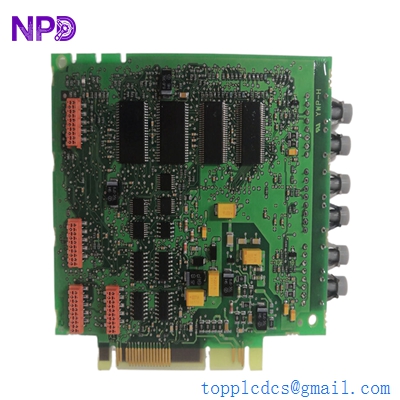
- Core Function: Operates as a specialized processing frequency I/O and voltage/current monitoring interface board, converting internal system output signals into deterministic drive telemetry to regulate multi-megawatt high-voltage converters.
- Condition: Brand New Surplus / High-Grade Clean Tested (Original anti-static moisture-barrier packaging)
- Product Type: Voltage/Current M ADCVI Control Processor PC Board
- Key Specs: 24V DC Rated Core System Logic | Multi-channel fast analog/frequency conversions | Direct optical or backplane integration rails
- Operating Input Voltage: 24V DC (\pm10\%, stabilized through internal filtering bus)
- Signal Capture Profile: Multi-channel voltage, current, and raw high-resolution frequency indexing (M ADCVI infrastructure)
- Galvanic Isolation Threshold: Embedded high-density optocoupler matrices to shield fragile control loops from medium/high-voltage power backplanes.
- Ambient Thermal Envelope: Continuous operations ranging from -20°C to 70°C inside sealed industrial cabinets.
- Diagnostic Interface Status Matrix: Integrated high-visibility LED fault tracking layout:
- Solid Red Indicator: Unresolved critical control loop trip or major micro-controller fault.
- Flashing Green Indicator: Non-fatal system anomaly warning or param-group logic alert.
- Cooling Profile: Natural convection cooling matching typical rack assembly requirements.
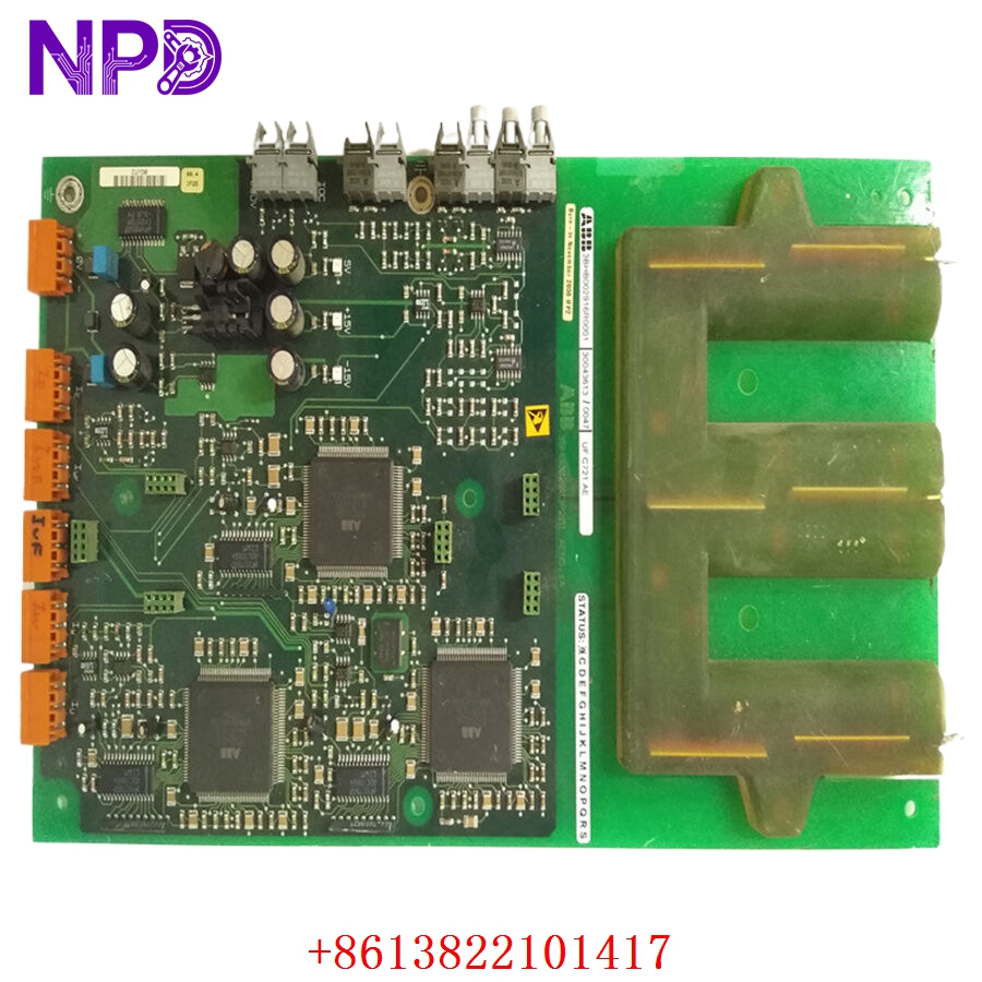
ABB 3BHB002916R0001 UFC721AE
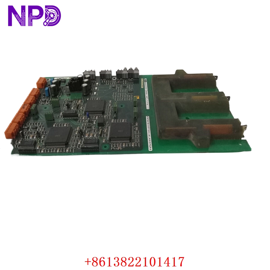
ABB 3BHB002916R0001 UFC721AE
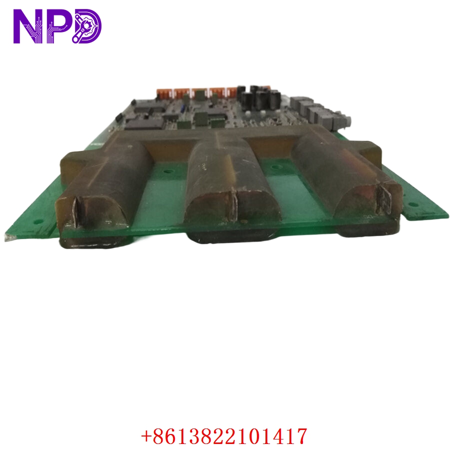
ABB 3BHB002916R0001 UFC721AE
Application Scenarios & Engineering Pain Points
The ABB UFC721AE 3BHB002916R0001 is deployed as a core system control component inside large high-voltage variable frequency drive (VFD) ecosystems. It bridges the gap between processing calculation algorithms and direct raw field diagnostics by acting as a high-speed frequency/analog capture gateway.
Because this board handles incoming voltage and frequency telemetry from highly dynamic mechanical arrays, it is susceptible to progressive thermal aging and signal trace degradation. In aggressive environments like steel mills, chemical facilities, or maritime power plants, continuous high-frequency vibration or micro-fluctuations in the 24V DC backplane feed line can induce micro-cracks in the onboard optocoupler connections or processing chips. When this occurs, the module begins outputting erratic data, causing the system to trip on “Phase Asymmetry,” “Overcurrent Ground Loop,” or “Commutation Timeouts,” halting critical production systems. Keeping a validated spare ready avoids prolonged outages during unplanned component failures.
Typical Industrial Deployments:
- Steel and Metal Rolling Mills – Governs precise speed feedback and current regulation loops on high-power reversing mills and motor tables.
- High-Voltage Pump and Compressor Stations – Coordinates frequency input parameters for massive water distribution networks and gas pipeline compressors.
- Automated Cement and Mining Kilns – Tracks complex torque and variable frequency loops on heavy, continuous-duty grinding mill drives.
Standard Operating Procedure (SOP) Quality Transparency
Every high-value industrial control PC board undergoes a multi-point component verification sequence inside our testing lab before it is approved for global shipping:
[Component Architecture Inspection] ➔ [Power Supply Stability Run] ➔ [Channel Data Accuracy Test] ➔ [Optocoupler Isolation Audit] ➔ [Anti-Static Vacuum Sealing] - Component Architecture Inspection
We audit the board under heavy magnification to verify trace continuity, terminal block thread health, and ensure no capacitor bulging or micro-solder fractures are present.
- Power Supply Stability Run
The board is seated in a test rack and continuously powered with a 24V DC source to confirm the internal power regulators run cool and draw standard, stable idle currents.
- Channel Data Accuracy Test
Using advanced frequency and analog simulation equipment, signals are fed into the input channels to verify that the digitized transmission packets stay inside factory calibration limits.
- Optocoupler Isolation Audit
High-potential isolation checks are executed across the barrier interfaces to confirm absolute protection against unexpected field voltage spikes.
- Anti-Static Vacuum Sealing
The verified card is enveloped in a thick ESD protective sleeve with active moisture absorbing desiccant and secured within a heavy corrugated carton box to ensure maximum safety during transport.
Technical Pitfall Mitigation Guide
When executing a hot-swap or field replacement of the UFC721AE 3BHB002916R0001, engineers must observe the following precautions:
- Static Charge Dissipation Protection
- The Risk: CMOS processing architectures on the card are highly sensitive to electrostatic discharge (ESD). Touching the board without adequate grounding can cause silent micro-damage to the IC units that shows up as sudden field failures days later.
- The Fix: Maintain a grounded wrist strap connection during handling and installation. Hold the board only by its structural card edges; do not make direct contact with backplane pin tracks or surface-mounted components.
- Capacitor Discharge Latency Delay
- The Risk: High-voltage converters house large capacitor arrays that retain dangerous energy levels even after the main isolation breakers are flipped.
- The Fix: Wait a minimum of 5 minutes after a full system power shutdown before sliding out the old board or cleaning surrounding rack configurations. Check with a reliable multimeter to confirm the bus voltage has bottomed out safely.
- Verify Parameter Configuration Mapping
- The Risk: Installing a fresh control card into a complex drive track without confirming parameter group profiles (such as Group 30/31 settings) can cause the system to misread external trip signals or cause unexpected motor spin-ups.
- The Fix: Connect your engineering workstation to backup the system parameter map prior to extraction. Once the new card is seated, upload the working profile configurations and verify that the external reset selections (e.g., Parameter 1604) map correctly to your control layout.