Description
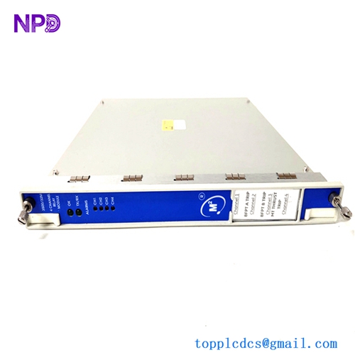
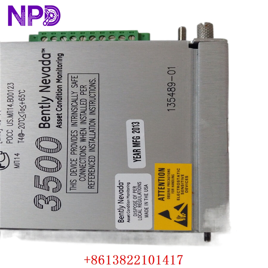
- Model: BENTLY NEVADA 135489-01
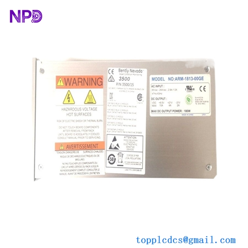
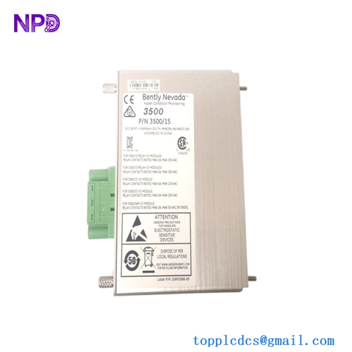
- Brand: Bently Nevada (USA / Baker Hughes)
- Series: 3500 Machinery Protection System (Compatible with 3500/42M, 3500/40M, 3500/70M, and 3500/72M)
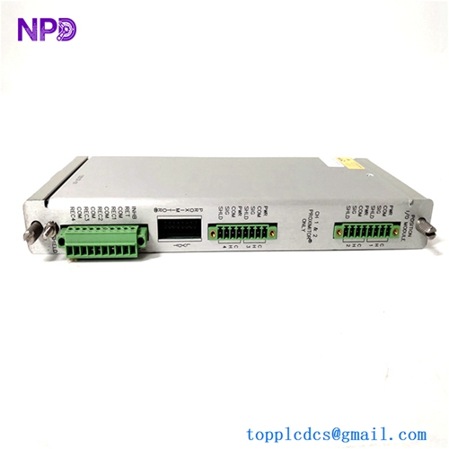
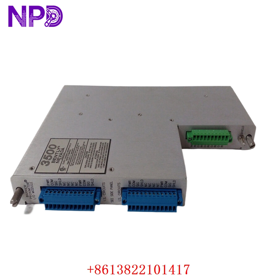
- Core Function: Rear-slot I/O module equipped with integrated intrinsically safe (IS) internal barriers for 4 proximity or acceleration transducer channels
- Condition: Brand New Surplus (Original factory authentic stock, never deployed, immaculate circuit board architecture)
- Product Type: 4-Channel Intrinsically Safe Monitor I/O Module
- Key Specs: Rear-rack mounting profile, internal terminations, built-in explosion protection networks, 4x Prox/Accel signal conditioning lines
- Module Interface Path: Connects directly through the rear slot of the 3500 machinery protection chassis cage
- Channel Density: 4 fully independent proximity probe or accelerometer input channels (Channels 1 through 4)
- Sensor Compatibility: Works with Bently Nevada 3300 XL 8mm, 5mm, 11mm, and NSv Proximitor sensor systems, plus standard industrial accelerometers
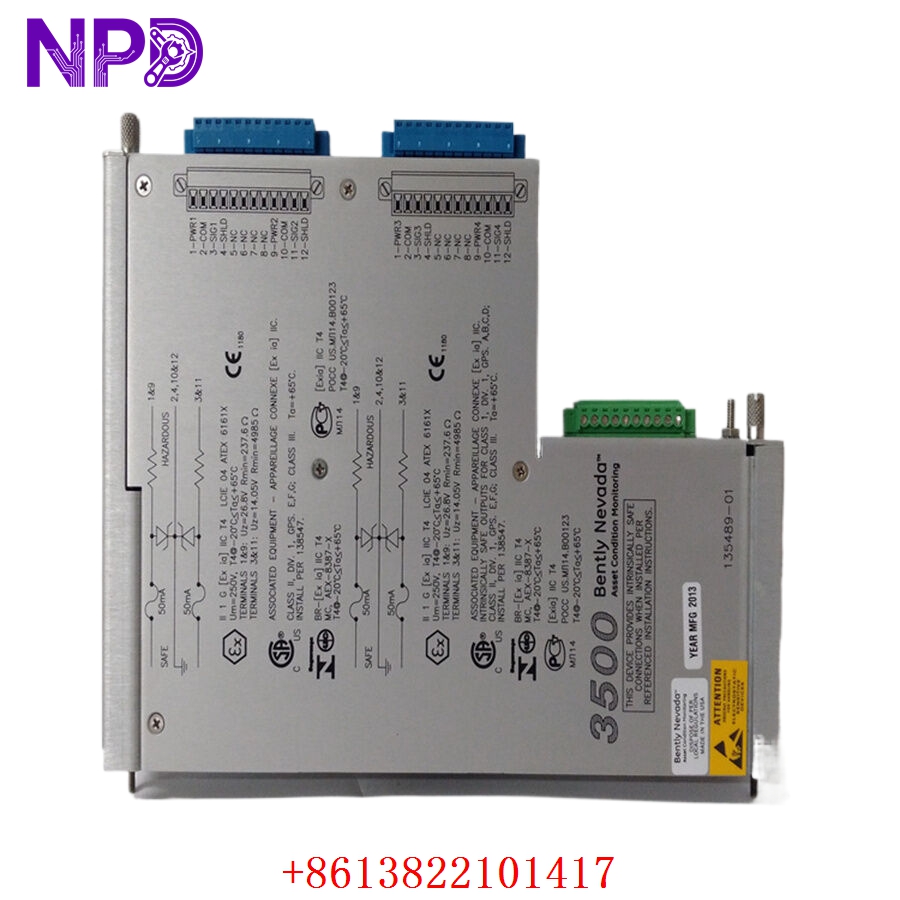
- Explosion Protection Type: Integrated Zener-diode style galvanically referenced internal safety barriers
- Intrinsic Safety Parameters: Maximum voltage output (U_o) = 26.8 V, Minimum resistance (R_{min}) = 237.6 \Omega, Maximum current (I_o) = 112.8 mA, Maximum power (P_o) = 625 mW
- Bandwidth Envelope: Up to 30 kHz signal throughput capacity
- Amplitude Tracking Accuracy: Within ±3% at 10 kHz, and -15% / +10% at 30 kHz peak frequencies
- Phase Accuracy Window: Within -11° displacement at 10 kHz signal frequencies
- Earth Framework Requirement: Requires direct integration with a 3500/04-01 Intrinsically Safe Earthing Module via the rack backplane
- Operating Temperature: -30°C to +65°C ambient air envelope
- Storage Temperature Envelope: -40°C to +85°C maximum limits
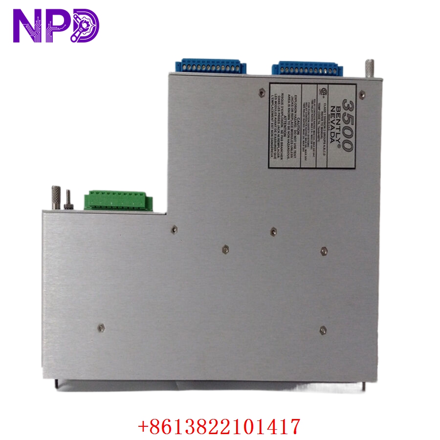
- Physical Depth Profile: Deep-profile Eurocard layout (adds approx. 50 mm / 2 inches of depth to the rear wiring envelope compared to standard non-barrier I/O boards)
BENTLY 135489-01
BENTLY 135489-01
BENTLY 135489-01
BENTLY 135489-01
Installation & Configuration Guide
Pre-Installation Setup
⚠️ CRITICAL SAFETY WARNING:
- Coordinate an asset monitoring bypass window with the operations control room before disturbing any sensor loops.
- Ensure that the 3500 rack includes an active 3500/04-01 IS Earthing Module to handle the ground path. Never power up an internal barrier module without a verified low-impedance master safety ground connection.
- Verify that your system enclosure has at least 50 mm of extra rear depth clearance. This card is deeper than standard cards to maintain safe separation distances.
- Ensure hazardous area field cables are physically separated from safe area control loops to comply with code requirements.
- Required Tools & Gear:
- Grounded anti-static wrist strap anchored directly to the local enclosure master copper ground bus.
- Standard 4.5 mm slot flathead screwdriver and a small terminal block torque tool.
- Digital multimeter (such as a Fluke 289) for tracking loop voltages.
- Portable calibration unit or signal injector (such as a TK-3 or Bently Nevada 3500 signal generator).
- 3500 Rack Configuration Software running on an engineering notebook terminal.
- Backup Procedures:
- Connect to the rack’s main controller interface, pull a full configuration file upload (.wcf format), and save a backup copy on your storage drive.
- Document the specific sensor types, scale factors, and calibration curves associated with the four active channels on the front monitor board.
Old I/O Board Removal
- Engage System Bypasses: Turn the physical rack keyswitch to the “Bypass” position or use the software workspace to inhibit all trip relay outputs.
- De-energize Field Cables: Unscrew the terminal blocks to disconnect the field sensor wires (Signal, Power, Common) from the rear of the card. Label each cable clearly with its matching channel assignment (Ch 1 to Ch 4).
- Loosen Retaining Screws: Back out the upper and lower captive fasteners that hold the rear I/O faceplate to the rack frame using your flathead screwdriver.
- Eject and Withdraw Card: Gently pull the card’s injection/ejection tabs outward to disengage the multi-pin edge connectors from the backplane assembly. Slide the module straight out of the track channels and place it on an ESD-safe workbench mat.
New Module Mounting and Configuration
- ESD Mitigation Check: Ensure your grounded wrist strap remains securely attached while removing the replacement 135489-01 board from its protective anti-static packaging.
- Inspect Keying Layout: Verify that the physical keying pins on the back of the card match the designated rear slot on your 3500 rack cage.
- Insert into Slot Track: Align the edges of the card with the upper and lower plastic guide tracks in the target slot. Slide the board smoothly backward into the rack chassis until the edge connectors meet the backplane.
- Seat and Secure Fasteners: Push the injection levers inward to fully seat the board’s pins into the backplane. Tighten the upper and lower captive faceplate screws down snug (to roughly 0.6 N·m torque) to lock the module in place and establish a solid frame ground connection.
- Terminate Sensor Leads: Reconnect your proximity probe or accelerometer field wires to their designated channel terminal screws. Ensure clean wire dressing and verify that no stray shielding threads bridge across adjacent terminals.
Post-Installation Verification Checklist
- [ ] Confirm that an active 3500/04-01 IS Earthing Module is fully operational within the chassis.
- [ ] Verify that all channel terminations match your plant wiring and instrumentation diagrams.
- [ ] Check that the card sits flush in the rack and both retaining screws are tightened down snug.
- [ ] Ensure that hazardous-area and safe-area signal wiring cables maintain the required 50 mm physical separation.
Power-Up & Loop Commissioning
- Return the 3500 rack power supply circuit breakers to the active ON position.
- Monitor the LEDs on the matching front-panel monitor card (such as a 3500/42M):
- OK (Green): Illuminates steady green after a successful startup sequence, indicating the front monitor and rear I/O board are communicating correctly.
- TX/RX (Green): Flashes rapidly, indicating continuous data processing across the internal backplane bus.
- BYPASS (Amber): Remains lit while the system is held in bypass mode during loop checkout operations.
- Open the 3500 Rack Configuration Software on your engineering notebook. Enter the configuration screen for the associated monitor slot and confirm that the software recognizes the new internal barrier module assembly.
- Verify that the sensor selection fields are set correctly for each channel (e.g., 3300 XL 8mm Proximitor, 200 mV/mil) to ensure the barrier circuitry scales the signals accurately. Download these parameters down to the rack’s non-volatile memory.
- Use your loop simulator to inject a dynamic test voltage into each channel terminal path. Confirm that the software workbench and connected HMI screens display the exact vibration or displacement values expected without any signal distortion or clipping.
- Check the DC gap voltages across all four proximity loops to ensure the internal Zener barrier drop is accounted for and the probes sit centered in their linear calibration ranges.
- Once all four loops test out clean, switch the rack back to “Run” mode, log the module’s serial number into your asset tracking records, and release the machine for standard operation.
Customer Cases & Industry Applications
Case 1: Petrochemical Refinery Hydrogen Compressor Protection
A major refinery along the Yangtze River loop experienced an unexpected internal component failure on an older I/O board that monitored its critical high-pressure hydrogen recycling compressor. Because hydrogen environments carry a high risk of explosion, the proximity probes must run through certified intrinsically safe barriers. The existing card failure dropped the safety monitoring paths, which created an immediate regulatory violation and put the facility at risk of a forced operational shutdown.
The local factory distribution network quoted a 10-week delivery timeline for a replacement module. To keep production moving, the refinery team reached out to check our surplus stock for a 135489-01 module. We pulled a brand-new surplus board from our shelves, verified its barrier safety circuits on our specialized 3500 evaluation rack, and shipped the part via priority air express that afternoon. The card arrived at the refinery the next morning. Technicians completed the swap, verified the safety earth paths, and brought the compressor’s vibration loops back online within 24 hours of their initial call.
Case 2: Offshore LNG Loading Terminal Turnaround Upgrade
During a scheduled maintenance turnaround at an offshore liquefied natural gas (LNG) terminal, inspection crews found that several external barrier enclosures on an LNG carrier loading platform showed signs of salt-air corrosion. The engineering team decided to eliminate these external terminal enclosures entirely and move the safety barriers inside the main control room by using Bently Nevada internal barrier cards.
[Corroded External Barrier Box] ──> [High Failure Risk & Maintenance Costs]
                                                 │
                 ┌───────────────────────────────┴───────────────────────────────┐
                 ▼                                                               ▼
   [Option A: Replace External Box]                                 [Option B: Internal Barrier Board Upgrade]
   • Cost: High field labor and parts expenses                     • Cost: ~50% savings on deployment overhead
   • Footprint: Bulky external enclosures remain                    • Footprint: Compact, clean slide-in design
   • Long-Term Risk: Ongoing exposure to marine air                • Long-Term Risk: Protected inside an air-conditioned room
The facility group needed three 135489-01 4-channel barrier modules to support the upgrade project. They ordered new surplus units from our inventory, complete with industrial-grade conformal coating to protect against environmental moisture. The team installed the modules directly into the existing rear slots of the 3500 racks, avoiding the need for external barrier hardware and complex field wiring re-runs. This update simplified their instrumentation architecture, improved system reliability, and completed right on schedule before the terminal restarted operations.
Frequently Asked Questions (FAQ)
Q1: What is the main difference between a standard 3500/42M I/O card and the 135489-01 card?
A: A standard I/O card passes sensor signals directly into the monitor board without any voltage-limiting or current-limiting safety networks, meaning the field lines must be routed through separate external barrier boxes if they go into a hazardous area. The 135489-01 card features built-in, intrinsically safe Zener barriers right on the circuit board. This design allows you to connect hazardous-area proximity probes directly to the rear of the 3500 rack without needing any external barrier components.
Q2: Why does my 3500 system show a configuration fault alarm after sliding this card into place?
A: This fault usually happens for two common reasons:
- The 3500 rack requires an active 3500/04-01 IS Earthing Module installed in the chassis to provide a safety ground path for internal barrier modules. If this earthing card is missing or not grounded correctly, the rack will flag a fault.
- The settings inside your 3500 Rack Configuration Software may still be configured for a standard I/O card. You will need to open the software, change the I/O module type selection to the internal barrier option, and download the updated configuration file to the rack.
Q3: How do you verify the functionality and safety ratings of these internal barrier cards before shipping?
A: We test every module through a rigorous process that goes far beyond simple continuity checks. We place each card onto a functional 3500 test framework and connect it to a high-precision loop analyzer.
[3500 Safety Test Rack] ──> [135489-01 Barrier Module] <──> [Loop Analyzer & Signal Injector]
                                                                    │
                                                                    ▼
                                                    [24-Hour Continuous Stress Test]
We inject accurate dynamic vibration signals across the full 30 kHz bandwidth to ensure the safety barrier components do not cause any signal loss or phase distortion. This comprehensive validation ensures that the module will provide both accurate measurements and reliable explosion protection from the moment it is installed.
Q4: Will this module fit inside a standard 400 mm deep control enclosure cabinet?
A: No, it generally will not fit a standard 400 mm cabinet. Because this card includes internal safety barrier circuitry, it extends out about 50 mm (2 inches) further than a standard non-barrier I/O module to maintain the required physical separation between safe and hazardous wiring paths. You will need a cabinet depth of at least 600 mm or a bulkhead-mounted rack configuration to allow enough room for proper cable routing and strain relief.
Q5: Can I mix proximity probes and accelerometers on the same 135489-01 module?
A: Yes, you can mix sensor types, but they must be configured in pairs (Channels 1 & 2 form one pair, and Channels 3 & 4 form another). For example, you can set up Channels 1 and 2 to process standard -24 V DC proximity probe signals, while configuring Channels 3 and 4 to handle positive-voltage constant-current accelerometers. Make sure your software selections match the physical sensors connected to those terminal pairs.
Q6: What payment and shipping methods do you offer for urgent emergency plant shutdowns?
A: We accept international wire transfers (T/T), corporate credit cards, and standard letters of credit. To help expedite emergency repairs, you can send us a copy of your bank’s wire transfer confirmation slip. Our logistics team will immediately pull the part from stock, run it through our engineering verification tests, and hand it off to an express courier like DHL or FedEx to minimize your facility’s downtime.