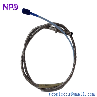
Description
- Model Code: BENTLY NEVADA 330104-00-05-10-02-00
- Brand: Bently Nevada (USA / Baker Hughes)
- Series: 3300 XL 8mm Proximity Transducer System
- Core Function: Non-contacting eddy current displacement sensor for measuring dynamic shaft vibration, axial position, eccentricity, and keyphasor timing on critical rotating machinery.
- Condition: Brand New Surplus (Original authentic factory stock, never deployed, complete with factory thread protectors, pristine physical condition)
- Product Type: 3/8-24 UNF Threaded Proximity Probe Assembly
The highly specific configuration for this model code breaks down exactly as follows:
- 330104: 3300 XL 8mm Probe, 3/8-24 UNF thread, without armor.
- -00: Unthreaded Length Option = 0.0 inches. (The entire case is threaded).
- -05: Overall Case Length Option = 0.5 inches.
- -10: Total Length Option = 1.0 meter (3.3 feet).
- -02: Connector Option = Miniature coaxial ClickLoc connector, fluid-resistant, standard thread.
- -00: Agency Approval Option = No special regional approvals required (Standard multi-certified base construction).
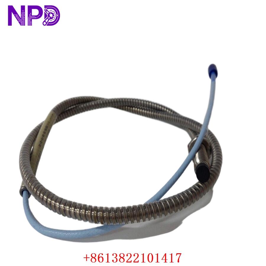
BENTLY 330104-00-05-10-02-00
BENTLY 330104-00-05-10-02-00
Key Technical Specifications
- Thread Profile Size: 3/8-24 UNF-2A overall threading
- Linear Measuring Range: 2.0 mm (80 mils), beginning at approximately 0.25 mm (10 mils) from the target face
- Scale Factor Sensitivity: Standard 7.87 V/mm (200 mV/mil) when combined with a matching 3300 XL Proximitor Sensor and extension cable
- System Component Tracking: Calibrated for standard AISI 4140 electric-furnace vacuum-melted steel targets
- Total Cable Base Length: 1.0 meter (±10% nominal compliance)
- Minimum Bend Radius: 25.4 mm (1.0 inch) for the standard coaxial configuration lines
- Dielectric Strength Isolation: 500 V RMS from the internal signal leads directly to the outer case shell
- Operating Temperature Range: -51°C to +177°C (-60°F to +350°F) ambient envelope for the probe head and cable assembly
- Environmental Sealing Boundaries: Hermetically sealed probe tip, rated to withstand up to 700 kPa (100 psi) differential pressure across the sensor face
- Connector Type Implementation: Gold-plated brass ClickLoc coaxial interface connection paths
Installation & Configuration Guide
Pre-Installation Setup
⚠️ CRITICAL SAFETY WARNING:
- Coordinate an asset tracking bypass window with the main machinery control room before opening terminal junction housings or loosening sensor mounts.
- Ensure all automated trip interlocks associated with this sensor channel are placed in manual override or software bypass to prevent an accidental asset trip.
- Verify that the rotating shaft is completely at rest or turning at slow roll speeds before setting probe gap tolerances to avoid contact damage to the sensor face.
- Required Tools & Gear:
- Grounded anti-static wrist strap connecting directly to the machinery casing frame earth.
- Digital multimeter (such as a Fluke 289) equipped with specialized insulation piercing taps or fine wire probes.
- Deep-well socket wrenches and matching open-end wrenches for 3/8-24 UNF hex backing nuts.
- Specialized non-magnetic feeler gauges or a mechanical dial indicator assembly.
- A dedicated 3300 XL calibration verification fluid-gap micrometer tool (such as a Bently Nevada TK-3).
- Backup Procedures:
- Prior to replacement, upload the complete rack parameter profile via the front port of the 3500/22 TDI module and save a backup file (.wcf).
- Document the historical running DC gap voltage and the precise physical insertion depth of the old probe.
Old Sensor Removal
- Isolate Channel Connections: Open the local weather-proof junction box. Disconnect the miniature ClickLoc coaxial joint joining the probe tail to the long extension cable loop.
- Loosen Locknuts: Use an open-end wrench to release the outer locknut securing the probe case inside the bracket or machine housing sleeve.
- Unthread Probe Body: Carefully spin the probe counterclockwise to unthread it from its mounting port. Keep the 1.0-meter cable tail rotating in unison with the probe body to prevent twisting, kinking, or tearing the inner conductors.
- Inspect Port Cavity: Once the old probe is out, clean the mounting hole thread track. Use a clean lint-free cloth to remove any oil lacquer deposits, metallic sludge, or carbon buildup.
New Sensor Mounting and Configuration
- ESD Mitigation Check: Wear your grounded static wrist strap while extracting the replacement 330104-00-05-10-02-00 probe assembly from its protective packaging. Keep the factory protective tip cap on until the final installation step.
- Pre-Thread Inspection: Thread a matching 3/8-24 hex backup nut onto the new probe body. Verify that it spins smoothly down the 0.5-inch threaded case section.
- Thread Into Port Guide: Gently guide the probe tip into the mounting port. Slowly turn the sensor body clockwise, ensuring the 1.0-meter cable tail spins freely without binding.
- Precise Physical Gapping:
- Method A (Mechanical): Rotate the probe until the tip makes gentle contact with the stationary shaft face. Back the probe out exactly 5.5 turns (which equates to roughly 1.27 mm / 50 mils of physical air gap space), positioning it directly in the middle of its linear calibration curve.
- Method B (Electrical – Recommended): Remove the protective tip cap. Plug the probe’s ClickLoc connector into the extension cable link to power the loop. Connect your digital multimeter to the “Prox” and “Com” test terminals on the front of the matching 3500 monitor card. Slowly thread the probe inward until the multimeter displays a steady reading of -10.00 V DC (±0.2 V DC tolerance window).
 [Probe Tip] ========> [1.27 mm / 50 mils Air Gap] <======== [Shaft Surface]
                                    │
                                    ▼
                     [Monitored Loop Target Output]
Target: -10.00 V DC - Locking the Assembly: Hold the probe body steady with a wrench to keep it from rotating. Tighten the 3/8-24 outer backup locknut down snug against the mounting frame to a torque of 4.5 N·m (40 in-lb). Do not overtighten, as excessive torque can deform the threaded sleeve or damage the internal sensor assembly.
Post-Installation Verification Checklist
- [ ] Confirm that the probe tail cable is free of tight bends, pinches, or sharp kinks.
- [ ] Verify the ClickLoc coaxial connector joint is pushed fully home and twisted to lock securely.
- [ ] Ensure the connector junction is insulated from the metal casing using clear heat-shrink tubing or a dedicated silicone boot.
- [ ] Verify that the outer mounting locknut is torqued down snug to prevent the sensor from backing out under machine vibration.
Loop Commissioning & Calibration Run
- Re-engage power to the 3500 monitoring system rack.
- Check the status indicator lights on the matching front-panel monitor card (such as a 3500/42M):
- OK (Green): Solid green indicates the channel loop impedance is within normal operational parameters.
- NOT OK (Amber): If this light is on, it typically means the DC gap voltage is out of range, the coaxial connector is loose, or there is a short circuit in the field wiring.
- Check your digital multimeter connected to the monitor card’s front test points. Confirm that the stable base DC gap voltage reads between -9.5 V DC and -10.5 V DC under static conditions.
- Using a calibration micrometer tool (like a TK-3), verify the scale sensitivity factor across the linear range. The output should shift by 1.00 V DC for every 0.127 mm (5 mils) of physical movement.
- Apply silicon self-fusing tape or install an insulation sleeve over the coaxial connector joint inside the local junction box to isolate it from the metal housing frame.
- Once the machinery returns to normal running speed, observe the dynamic AC vibration waveforms on your engineering workstation screen. Ensure the signal tracks clearly without any clipping, signal dropouts, or high-frequency noise.
- Clear any active latching alarms on the HMI terminal, update your asset management maintenance records with the new serial number, and sign the channel off as fully operational.
Customer Cases & Industry Applications
Case 1: Power Plant Boiler Feed Pump Radial Vibration Restoration
An electric utility power station in South Texas experienced a sudden “Sensor Not OK” fault on a high-speed boiler feed pump monitoring loop. The failure of this vibration probe left a critical auxiliary pump unprotected, meaning any unexpected shaft displacement could go unnoticed and potentially cause severe bearing damage.
The OEM parts network quoted an 8-week delivery lead time for a replacement probe. To avoid operating without critical machinery protection, the plant’s maintenance group contacted us to check our ready surplus inventory for a 330104-00-05-10-02-00 probe. We pulled a brand-new surplus unit from our stock, verified its electrical characteristics and scale factor on our precision eddy-current calibration bench, and shipped it via overnight air express. The probe arrived at the site the following morning. Technicians installed the sensor, set the DC gap voltage to -10.00 V DC, and restored the vibration monitoring loop to full operation within 24 hours of the initial fault.
Case 2: Chemical Center Ethylene Compressor Turnaround Optimization
During a scheduled maintenance turnaround at a Gulf Coast petrochemical facility, engineering crews discovered that an axial position probe on a primary ethylene compressor had sustained outer casing wear due to exposure to high-velocity oily mist. The maintenance team decided to replace the worn sensor immediately to prevent any signal degradation during the upcoming production cycle.
[Oily Mist Outer Casing Wear] ──> [Potential Signal Degradation Risk]
                                                │
                ┌───────────────────────────────┴───────────────────────────────┐
                ▼                                                               ▼
  [Option A: Full System Upgrade]                                  [Option B: Direct Surplus Component Swap]
  • Cost: High capital expenditure (~$45,000)                      • Cost: ~80% savings compared to upgrade path
  • Downtime: 2 days of panel modifications                        • Downtime: Installed and gap-set in <30 minutes
  • Execution Risk: High software integration effort               • Execution Risk: Drop-in match, zero wiring changes
The facility required an exact hardware match to ensure seamless integration with their existing 3300 XL Proximitor configurations without altering any software settings. They ordered a new surplus 330104-00-05-10-02-00 probe from our inventory. The instrumentation crew completed the drop-in swap, locked the case threads, and verified the calibration curve in under thirty minutes. This quick and reliable replacement allowed the facility to wrap up their maintenance turnaround right on schedule and restart production without delay.
Frequently Asked Questions (FAQ)
Q1: What do the “-00” and “-05” options in the part number indicate?
A: These codes define the physical dimensions of the probe’s metal casing. The -00 option specifies that the unthreaded length is 0.0 inches, meaning the entire body of the probe is threaded. The -05 option indicates that the overall case length is 0.5 inches. This short-case configuration is ideal for compact mounting locations or low-profile bracket assemblies where space is limited.
Q2: Can this 1.0-meter probe be connected directly to a 3500 system monitor card without an extension cable?
A: No, it cannot be connected directly. Bently Nevada 3300 XL 8mm proximity transducer systems are calibrated to operate with a specific total electrical length—either 5.0 meters or 9.0 meters. Because this probe has a built-in cable length of 1.0 meter, you must use a matching 4.0-meter or 8.0-meter extension cable to connect it to the Proximitor sensor module. Connecting the probe without the correct extension cable will cause severe calibration errors and trip the “Monitor Not OK” alarm.
Q3: How do you verify the physical condition and linear calibration of these probes before shipping?
A: Our testing process goes far beyond a simple visual check. We place every surplus probe onto a specialized eddy-current calibration stand equipped with a standard AISI 4140 steel target block.
[Precision Calibration Stand] ──> [330104 Probe Under Test] <──> [AISI 4140 Target Block]
                                                                        │
                                                                        ▼
                                                       [Automated 80-Mil Voltage Sweep]
We run an automated voltage sweep across the entire 80-mil linear range to confirm that the sensor maintains its rated 200 mV/mil scale sensitivity factor within strict factory tolerances. This comprehensive testing ensures that the probe will provide highly accurate vibration and position data from the moment it is deployed.
Q4: Is this probe compatible with older 3300 series Proximitor sensors?
A: Yes, the 3300 XL 8mm probe is backward compatible with standard older 3300 series Proximitor sensors. However, for optimum performance and reduced temperature drift, we recommend pairing it with a matching 3300 XL series Proximitor sensor. Always verify that the total system length (5.0 or 9.0 meters) matches the rating stamped on your specific Proximitor module.
Q5: Why is it critical to insulate the ClickLoc coaxial connector joint inside the junction box?
A: The outer brass shell of the ClickLoc connector carries the active signal return path. If this metal shell comes into contact with a grounded junction box or structural steel plate, it will short-circuit the sensor loop. This causes the DC gap voltage to drop to 0.0 V DC, immediately triggering a “Not OK” system alarm and disabling machinery protection for that channel. Always use clear heat-shrink tubing or an insulation boot to isolate this connection.
Q6: What payment and shipping methods are available for urgent refinery orders?
A: We accept international wire transfers (T/T), corporate credit cards, and standard letters of credit. For emergency plant shutdowns, send over a copy of your bank’s wire transfer confirmation slip. Our logistics team will immediately pull the part from our stock, complete our quality verification testing, and hand it off to an express air courier (like DHL or FedEx) to minimize your facility’s downtime.