
Description
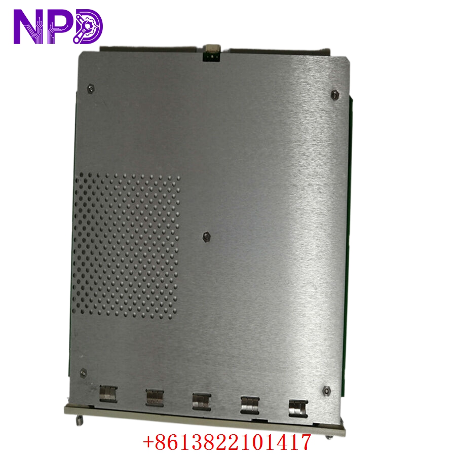
- Model: BENTLY NEVADA 3500/22M (Commonly associated with mainboard part number 146031-01 and I/O modules 146077-01 / 147364-01)
- Brand: Bently Nevada (USA / Baker Hughes)
- Series: 3500 Machinery Protection System
- Core Function: The Transient Data Interface (TDI) acts as the primary gateway module for the 3500 rack, bridging core backplane data with external configuration software, system computers, and condition monitoring networks (System 1). It continuously collects static and dynamic (transient) waveform data for diagnostic evaluation.
- Condition: Brand New Surplus (Original authentic factory stock, zero field hours, unconfigured)
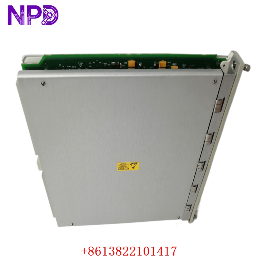
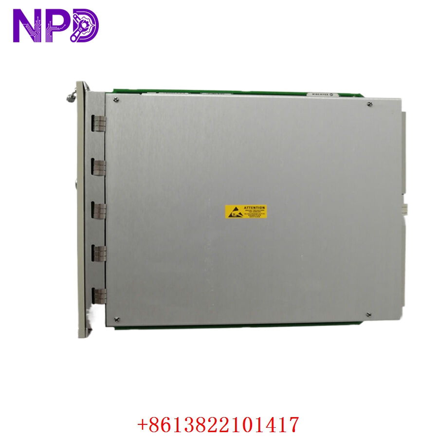
- Product Type: Transient Data Interface (TDI) Processing Module
- Operating Input Voltage: Power derived directly through the 3500 rack backplane (+5 V DC and +24 V DC rails)
- Power Dissipation: 8.5 W nominal processing load limits
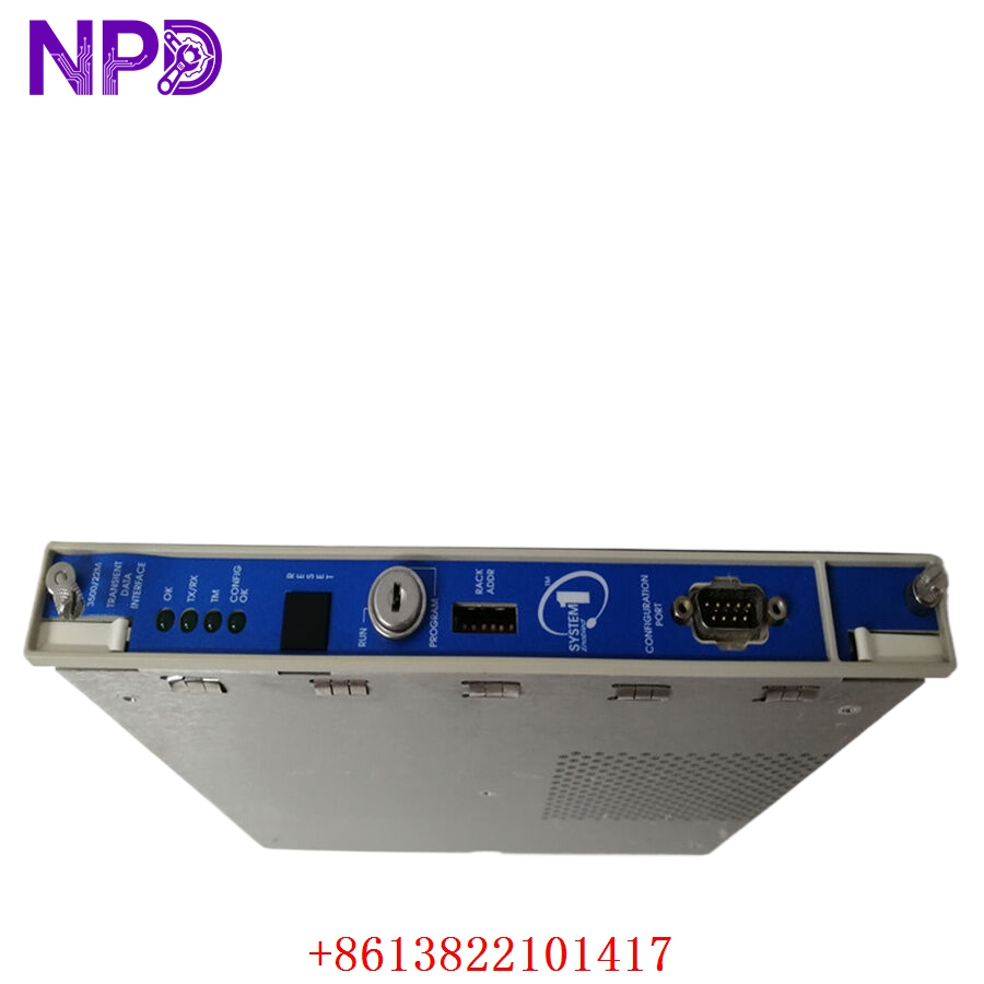
- Communication Ports:
- Front Panel: 1x USB Type-B port for direct engineering terminal connectivity
- Rear I/O (Standard): 1x 10/104Base-T Ethernet RJ45 port, 1x RS232/RS422 serial communications port (DB9 setup)
- Protocol Support: Modbus RTU, Modbus TCP/IP, and proprietary Bently Nevada high-speed host protocols
- Data Extraction Capability: Collects both static data (Direct variables, gap voltages, OK status) and dynamic/transient waveforms (Startup/Shutdown speed profiles, wave vectors, spectral snapshots)
- Operating Temperature: -30°C to +65°C ambient air envelope
- Storage Temperature Envelope: -40°C to +85°C maximum limits
- Humidity Tolerance: 5% to 95% relative humidity (RH, non-condensing)
- Conformal Coating: Premium industrial PCB layout coating for corrosive atmosphere protection
- Diagnostics: Real-time backplane line checking, hardware watchdog tracking arrays, and comprehensive system event logging
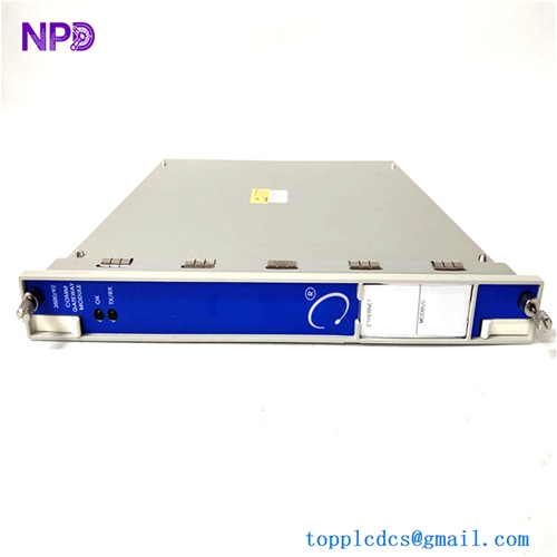
BENTLY 3500/22M
BENTLY 3500/22M
BENTLY 3500/22M
BENTLY 3500/22M
Installation & Configuration Guide
Pre-Installation Setup
⚠️ CRITICAL SAFETY WARNING:
- Coordinate a comprehensive monitoring bypass window with the operations control team before replacing a TDI module. While the 3500/22M does not directly execute relay trip logic, unseating it will cause a total loss of HMI data mapping, remote visibility, and event logging.
- Ensure the rack hardware keyswitch is available. You will need to switch it into “Program” mode during the module setup phase.
- Verify that the matching rear I/O card matches the interface type of your replacement (e.g., standard Ethernet vs. specialized fiber connections).
- Required Tools & Gear:
- Grounded anti-static wrist strap anchored directly to the local enclosure cabinet steel frame.
- Standard 4.5 mm flathead slot screwdriver for chassis panel screws.
- Windows engineering laptop running Bently Nevada 3500 Rack Configuration Software and an empty USB Type-B cable link.
- Digital multimeter (such as a Fluke 179) for checking network link voltage bounds if serial lines are utilized.
- Backup Procedures:
- Connect your laptop to the existing 3500/22M front port (if it is still intermittently operational). Upload and save the complete system architecture configuration file (.wcf file) to your hard drive.
- Document the precise IP address, Subnet Mask, Gateway, and Modbus register mapping structure currently running on the network loop.
Old Module Removal
- Turn the Rack Keyswitch: Insert the physical key into the 3500/20 or 3500/22 front faceplate slot and rotate it to the Bypass/Program position to suppress unauthorized network errors.
- Disconnect Cabling: Disconnect the front configuration links or rear network lines (Ethernet patch cables, serial DB9 extensions). Label each line clearly to prevent communication port mix-ups later.
- Loosen Retaining Screws: Back out the captive screws at the top and bottom of the 3500/22M front module plate using your flathead screwdriver.
- Eject and Withdraw: Pull the module’s top and bottom injection/ejection handles outward at the same time to unseat the board pins from the backplane. Slide the card smoothly forward out of the chassis tracks and place it on an ESD-protected workbench surface.
New Module Mounting and Configuration
- ESD Mitigation Check: Wear your grounded anti-static wrist strap when removing the new 3500/22M module from its anti-static shielding packaging. Avoid touching any open component traces on the PCB.
- Verify Internal Jumpers: Check the jumper orientations on the module’s circuit board. These jumpers control the RS232/RS422 serial line configurations and terminate communication lines. Match them exactly to your old board’s layout.
- Insert into Chassis Track: Align the top and bottom edges of the new card with the empty slot track guides (always designated in the slot immediately to the right of the power supplies). Slide the module smoothly backward into the rack chassis until the edge connectors meet the backplane.
- Seat and Secure Fasteners: Push the injection levers inward to fully seat the board’s pins into the backplane. Tighten the upper and lower captive faceplate screws down snug (to roughly 0.6 N·m torque) to lock the module in place and establish a solid frame ground connection.
- Reconnect Network Lines: Securely plug your Ethernet or serial cables back into their matching rear I/O matrix ports.
Post-Installation Verification Checklist
- [ ] Confirm that all onboard communication configuration jumpers match the original board’s settings perfectly.
- [ ] Verify that front panel retaining screws are completely threaded down snug.
- [ ] Ensure all communication cables are securely connected to their designated rear interface ports.
- [ ] Verify that the main system rack key is inserted and turned to the “Program” position.
Power-Up & Loop Commissioning
- The 3500 system backplane will automatically energize the 3500/22M module upon insertion if the rack power supply is active.
- Observe the front-facing LED diagnostics assembly array:
- OK (Green): Illuminates steady green after initialization, indicating the internal core microcontrollers passed self-test diagnostics.
- TX/RX (Green): Flashes rapidly, tracking real-time backplane data communications with the neighboring monitoring cards.
- TM (True Monitor – Amber): Illuminates when the rack is in a valid operational state and interacting properly with System 1 configuration clients.
- CONFIG FAULT (Red): Illuminates if the card recognizes an empty parameters block or an unaligned slot setup map.
- Connect your engineering notebook to the front USB Type-B port of the new module. Launch your 3500 Rack Configuration Software.
- Open your saved configuration file (.wcf profile) and enter the Network Configuration utility tab. Ensure the IP settings, gateway parameters, and Modbus tables are correctly defined.
- Execute a “Download Configuration to Rack” command sequence. The system software will prompt you to verify the hardware write action.
- Once the download completes successfully, the red CONFIG FAULT LED will turn off immediately.
- Turn the physical rack keyswitch back to the RUN position. This locks the parameter registers and protects them from accidental overrides.
- Check your plant DCS or HMI system network nodes. Confirm that all vibration variables, gap voltages, and channel alarms populate accurately across the network screens without data drops. Log the new serial number into your maintenance database to complete the commissioning process.
Customer Cases & Industry Applications
Case 1: Power Generation Center HMI Data Link Recovery
A gas-turbine power station in eastern China experienced a sudden communication dropout on its main control room HMI screens. The system lost visibility of all critical bearing vibration loops on a 150 MW generator set. While the 3500 monitoring rack continued to protect the machine locally via its hardware relay cards, the operators were left “flying blind” without real-time trends or alarm event logging. The diagnostic logs flagged a catastrophic processing failure on the rack’s primary 3500/22M TDI card.
The regional factory distribution network quoted an 11-week delivery timeline for a replacement module. To restore critical operational visibility before a peak power generation window, the plant’s maintenance group contacted us to check our ready surplus stock for an 146031-01 / 3500/22M module. We pulled a brand-new surplus card from our inventory, verified its communication ports and backplane routing logic on our testing framework, and shipped it via priority air express that afternoon. The card arrived at the station the next morning. Technicians completed the swap, downloaded the system architecture configuration file, and restored full data visibility to the control room within 24 hours of the initial failure.
Case 2: Chemical Center Petrochemical Compressor Monitoring Integration
During a plant turnaround at a large chemical center along the Gulf Coast, engineers upgraded their machinery diagnostics system to integrate multiple critical hyper-compressors with Bently Nevada’s System 1 predictive maintenance software. The old interface modules installed in the machinery racks did not feature the upgraded 3500/22M standard, which was required to support the high-density transient wave data transmission profiles needed for advanced cross-phase diagnostics.
[Legacy Interface Modules] ──> [Incompatible with High-Density Transient Data]
                                               │
               ┌───────────────────────────────┴───────────────────────────────┐
               ▼                                                               ▼
 [Option A: Full System Upgrade]                                 [Option B: 3500/22M Drop-In Upgrade]
 • Cost: High capital expenditure (~$95,000)                     • Cost: ~65% savings vs full upgrade path
 • Downtime: 4 days of extensive panel modifications             • Downtime: Completed in under 30 minutes per rack
 • Execution Risk: High loop recoding workload                   • Execution Risk: Zero wiring or monitor card changes
The facility needed an upgrade solution that would not require replacing their existing, fully functional vibration monitor cards or field sensor loops. They chose to source three brand-new surplus 3500/22M modules from our inventory. The instrumentation crew completed the quick drop-in hardware swaps, transferred the existing channel configurations using the configuration utility, and enabled the high-speed Ethernet communication links. This upgrade allowed the facility to seamlessly stream detailed transient waveforms into their System 1 platform, completing the predictive maintenance integration on schedule and well within budget.
Frequently Asked Questions (FAQ)
Q1: What is the functional difference between the older 3500/22 and the upgraded 3500/22M module?
A: The “M” designation stands for Modified/Upgraded processing capability. While both modules perform the same core role of managing rack data, the 3500/22M features significantly faster internal processors, expanded non-volatile memory architectures, and enhanced data transmission speeds via its integrated Ethernet paths. This increased bandwidth allows the 3500/22M to capture and stream high-resolution transient wave files (such as detailed shaft centerlines and orbit plots) to System 1 software without causing communication lag or data bottlenecks on the rack backplane.
Q2: Does the 3500/22M module arrive pre-loaded with our facility’s specific Modbus registers and network IP addresses?
A: No, these modules do not ship with facility-specific parameters pre-loaded. The unit is provided as brand-new surplus hardware containing only its base factory bootloader and core system diagnostic utilities. Once you slide the board into your rack slot, you must connect a laptop running the Bently Nevada 3500 Rack Configuration Software via the front USB port to download your project’s specific network configurations, slot assignments, and Modbus registers.
Q3: How do you verify the functionality of the communication ports and data paths before shipping?
A: Our testing process goes far beyond a simple visual check. We place every surplus module into an authentic 3500 rack frame and connect it to an automated loop simulator.
[3500 Test Rack Frame] ──> [3500/22M TDI Module] <──> [Modbus & System 1 Simulators]
                                                               │
                                                               ▼
                                              [24-Hour Continuous Stress Test]
We establish simultaneous communication links across the front USB port, rear Ethernet port, and serial interfaces. We then run a continuous 24-hour data stress test, transferring large packets of simulated transient wave data to confirm that the processor maintains stable connection links without any packet loss or port errors. This testing ensures the card will communicate reliably with your control network from the moment it is deployed.
Q4: Can I use my old 3500/22 rear I/O module with the new 3500/22M front processing card?
A: Generally, no. The upgraded 3500/22M front processing card must be paired with its matching upgraded rear I/O module (such as part number 146077-01 for standard Ethernet connections) to ensure proper pin alignment and support the higher data rates. When purchasing a replacement or upgrade, always verify that the front card and rear I/O module versions match to prevent backplane configuration errors or communication faults.
Q5: What does a blinking red CONFIG FAULT LED on the front panel indicate?
A: A blinking or solid red configuration fault light indicates that the module recognizes a mismatch between its stored configuration file and the physical hardware installed in the rack. This can happen if you add or remove monitor cards without updating the rack layout configuration file, or if the firmware version on the 3500/22M does not match the revision level expected by your configuration software. Downloading an updated .wcf file that matches the physical rack layout will clear this error.
Q6: What payment and shipping methods do you offer for urgent emergency plant shutdowns?
A: We accept international wire transfers (T/T), corporate credit cards, and standard letters of credit. For emergency repairs during an unplanned outage, send over a copy of your bank’s wire transfer confirmation slip. Our logistics team will immediately pull the part from our stock, complete our quality verification testing, and hand it off to an express air courier (like DHL or FedEx) to minimize your facility’s downtime.