Description
📋 Product Description
The DEIF MDR-2 is a multi-differential protection relay designed to protect three-phase generators and electric motors against internal short circuits, earth faults, and abnormal differential current conditions. It monitors current transformer signals from both sides of the protected equipment and evaluates current imbalance to support warning and tripping functions. The relay features adjustable differential protection characteristics, configurable alarm and trip settings, an integrated display for measured values, and an event history for commissioning and fault diagnosis. Depending on the ordered configuration, additional functions may include overcurrent, short-circuit, and block differential protection. It is suitable for generator protection systems in marine, industrial, and power-generation applications. Confirm the installed options and terminal configuration before using the unit as a replacement.
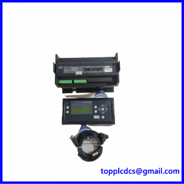
MDR-2
⚙️ Key Technical Specifications
- Brand: DEIF
- Model: MDR-2
- Product Series: Multi-Line 2
- Product Name: Multi-Differential Protection Relay
- Protection Functions: Differential current protection; optional overcurrent, short-circuit, and block differential protection
- Auxiliary Supply: 12/24 V DC nominal; 8–36 V DC operational range
- Measuring Inputs: Current transformer inputs for 1 A or 5 A secondary signals
- Binary Inputs: 6–32 V DC
- Relay Outputs: Configuration-dependent; verify the actual terminal and output ratings
- Operating Temperature: -25 to +70°C
- Mounting: DIN-rail or base mounting
- Weight: Approximately 1 kg, including packing, according to reference documentation
- Dimensions: Confirm from the product drawing and actual unit
- Product Status: Used, according to the referenced listing; manufacturer documentation currently identifies the MDR-2 as an active product
- Country of Origin: Confirm from the product nameplate
Additional identification details shown on the referenced listing include order number 100216238.150. Check the complete order number, hardware configuration, and installed options before ordering.
🏭 Application Scenarios & Pain Points
- Generator differential protection: Detects current imbalance between the generator-side measurement points and helps identify internal winding faults.
- Marine power systems: Supports generator protection in shipboard electrical distribution and power-generation installations.
- Industrial motor protection: Can be applied to compatible three-phase motor differential protection arrangements.
- Commissioning and troubleshooting: The integrated display provides access to measured values and historical alarms, helping technicians investigate protection events.
- Transformer and generator-block protection: Available block differential protection options can support specified generator and step-up transformer arrangements.
🔧 Installation & Operating Instructions
1. Installation Preparation
- Confirm that the MDR-2 model, order number, protection options, and wiring arrangement match the approved system drawings.
- Isolate the generator, control supply, and associated current transformer circuits before installation.
- Mount the unit on a suitable DIN rail or base according to the manufacturer’s installation instructions.
- Verify CT ratios, polarity, phase identification, and secondary ratings. Never leave an energized current transformer secondary open-circuit.
- Check auxiliary supply polarity and confirm that the DC supply is within the specified operating range.
2. Power-On Sequence
- Inspect terminal connections, protective fuses, grounding, and wiring insulation.
- Apply the specified auxiliary DC supply.
- Allow the relay to complete its startup checks.
- Check the display and system status indications for alarms or abnormal conditions.
- Confirm that all current measurements and binary input states are plausible before enabling protection trips.
3. Normal Operating Procedure
- Monitor the measured phase currents and differential current values on the display.
- Check system status and alarm indications during generator operation.
- Confirm that warning and trip functions respond according to the approved protection settings.
- Review the event history after an alarm or trip to help identify the cause.
- Do not bypass protection functions or reset a trip until the fault has been investigated and the equipment is safe to restart.
4. Shutdown Procedure
- Transfer the generator or motor to a safe operating condition according to the plant procedure.
- Disable the associated protection circuit where required by the approved shutdown sequence.
- Isolate the auxiliary DC supply before removing wiring or servicing the relay.
- Follow the current transformer safety procedure before disconnecting CT circuits.
5. Parameter Setting and Modification
- Access the relay configuration through the supported display or service interface.
- Set CT ratios, rated current, warning thresholds, trip thresholds, and time delays according to the approved protection study.
- Configure optional protection functions only when the corresponding hardware and software options are installed.
- Record the original settings before making changes.
- Verify all settings through secondary injection or an approved commissioning test before returning the equipment to service.
🛠️ Maintenance & Troubleshooting
- Periodically inspect terminal tightness, wiring condition, enclosure cleanliness, and mounting security.
- Check measured current values against calibrated reference instruments during scheduled maintenance.
- Investigate phase imbalance, incorrect CT polarity, loose wiring, or incorrect CT ratios if differential alarms occur.
- Review event records and protection settings when unexpected trips are reported.
- If the display or relay does not start, verify the DC supply, fuse, polarity, and wiring before suspecting an internal fault.
- Use qualified protection technicians and approved test equipment for secondary injection and functional testing.
⚠️ Safety Precautions
- Installation, configuration, and testing must be performed by qualified electrical or protection personnel.
- Dangerous voltages and currents may be present at the terminals even when the generator is stopped.
- Never open-circuit an energized CT secondary.
- Do not apply voltage outside the specified input ratings.
- Confirm relay contact ratings and terminal assignments from the applicable wiring diagram.
- Do not assume that different MDR-2 option configurations have identical functions or terminal layouts.
- Verify the complete protection scheme before commissioning or returning the system to service.
🔄 Related DEIF Models & Product Families
The following are other DEIF products that may be relevant to generator control, protection, monitoring, or power-management projects. They are not confirmed direct replacements for the MDR-2.
- DEIF AGC 150 – Automatic Genset Controller
- DEIF AGC 200 – Automatic Genset Controller
- DEIF AGC 202 – Generator Controller
- DEIF AGC 212 – Generator Controller
- DEIF AGC 222 – Generator Controller
- DEIF AGC 242 – Advanced Genset Controller
- DEIF AGC 243 – Advanced Genset Controller
- DEIF AGC 245 – Advanced Genset Controller
- DEIF AGC 246 – Advanced Genset Controller
- DEIF GPU-3 – Generator Protection Unit
- DEIF GPU-3 Hydro – Hydro Generator Protection Unit
- DEIF GPU-3 Gas – Gas Generator Protection Unit
- DEIF PPU-3 – Protection and Paralleling Unit
- DEIF PPM-3 – Power Management Unit
- DEIF MVR-200 – Voltage Protection Relay
Replacement Note: These models serve different control and protection functions. Verify application requirements, electrical ratings, communication interfaces, protection functions, and configuration before selecting an alternative.