Description
Product Description
The Flowserve GESTRA NRS 1-51 is an electronic level switch designed for high-water-level alarm and limiting applications in industrial steam boilers and process systems. It works with a compatible GESTRA NRG 1…-51 level electrode to monitor electrically conductive liquids and activate safety-related control circuits when the specified high-level condition is reached. The unit provides two separate control-circuit outputs, external alarm signaling, diagnostic LEDs, and a test button for functional checks. Depending on the ordered configuration, the supply can be 24 V DC or an optional 100–240 V AC version. The NRS 1-51 is designed for DIN rail mounting and supports response-sensitivity configurations for different water conductivity ranges. This listing identifies the item as used equipment removed from a working control enclosure and stocked in the UK; the electrode and other external accessories are not confirmed as included.
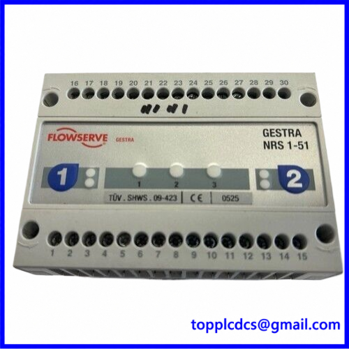
NRS 1-51
Key Product Parameters
- Brand: Flowserve GESTRA
- Model: NRS 1-51
- Product Series: GESTRA SPECTORmodul
- Product Type: Electronic High-Level Alarm Level Switch
- Primary Function: High-water-level detection and alarm
- Compatible Level Electrode: GESTRA NRG 1…-51 series
- Supply Voltage: 24 V DC ±20%, 0.3 A
- Optional AC Supply: 100–240 V AC +10%/-15%, 47–63 Hz, 0.2 A; verify the actual unit’s nameplate
- Power Consumption: 7 VA
- External Fuse: 0.5 A, semi-time-delay
- Response Sensitivity: Greater than 0.5 to less than 1,000 µS/cm, or greater than 10 to less than 10,000 µS/cm, depending on configuration
- Electrode Input: Compatible conductive level electrode input
- Control Circuit: Two separate safety-related control-circuit connections
- External Alarm Output: 24 V DC, maximum 100 mA, semiconductor output
- Standby Input: 18–36 V DC, volt-free input arrangement as specified in the wiring documentation
- Maximum Standby Bypass Time: 5 minutes
- De-Energizing Delay: 3 seconds, factory setting
- Indicators: Operating-status and diagnostic LEDs
- Controls: Test and diagnostic pushbutton
- Mounting: TH 35 DIN rail, EN 60715
- Housing Protection: IP40
- Terminal Protection: IP20
- Ambient Operating Temperature: -10 to 55°C
- Approximate Weight: 0.5 kg
- Dimensions: Approximately 100 × 120 × 73 mm
- Product Condition: Used, removed from a working control enclosure, according to the seller
- Stock Location: United Kingdom, according to the listing
- Country of Manufacture: Germany, according to GESTRA product documentation
- Discontinued: Verify current availability and support with GESTRA
Operating Procedures and Usage Instructions
1. Installation Preparation
- Confirm the complete model designation NRS 1-51.
- Read the nameplate to identify the actual supply-voltage version and response sensitivity.
- Verify compatibility with the installed GESTRA NRG 1…-51 level electrode.
- Confirm the boiler or process-system safety design and the required high-level alarm function.
- Check the electrical drawings, terminal assignments, external fuses, and control-circuit arrangement.
- Inspect the housing, detachable terminal strips, DIN rail clips, and terminal labels for damage.
2. Mechanical Installation
- Isolate the power supply before mounting the level switch.
- Install the NRS 1-51 on a standard TH 35 DIN rail.
- Secure the housing and allow adequate space for wiring and terminal-strip removal.
- Install the unit inside a suitable control cabinet.
- Maintain the specified environmental conditions and protect the unit from condensation and contamination.
3. Electrical Wiring
- Disconnect all power before connecting or removing terminal strips.
- Connect the supply voltage according to the actual nameplate: 24 V DC or the optional 100–240 V AC version.
- Use a safety extra-low-voltage (SELV) supply for the 24 V DC version.
- Connect the compatible NRG 1…-51 electrode using the specified screened cable.
- For the 10 µS/cm sensitivity configuration, use screened multicore control cable with a minimum conductor size of 0.5 mm² and a maximum cable length of 100 m.
- For the 0.5 µS/cm sensitivity configuration, use the specified double-screened, low-capacitance cable, with a maximum length of 30 m.
- Connect both safety control circuits according to the approved boiler protection design.
- Connect external alarm signaling and the standby input only where required by the system.
- Apply the specified external fuses and grounding arrangements.
- Do not interchange terminal connections between different NRS product versions.
4. Startup and Commissioning
- Verify supply voltage, terminal wiring, electrode connection, and fuse ratings.
- Energize the unit according to the manufacturer’s commissioning procedure.
- Check the green operating indicator and red alarm/diagnostic indicators.
- Use the test button to perform the prescribed functional test.
- Verify that the level electrode responds correctly to the actual water-level condition.
- Test both safety control circuits and the external alarm output.
- Confirm the configured response sensitivity and switching delay.
- Record commissioning results and the electrode/controller identification.
5. Normal Operation
- Monitor the operating and diagnostic LEDs during boiler operation.
- Check that the level electrode and switch respond correctly to changes in water level.
- Confirm that both control circuits remain in their intended operating state.
- Investigate any alarm or diagnostic indication before resetting the system.
- Do not bypass a high-level protection function during normal operation.
6. Configuration and Functional Testing
- Confirm the response-sensitivity configuration against the actual water conductivity and electrode specification.
- Follow the GESTRA commissioning instructions when testing switching behavior.
- Verify the external alarm circuit and downstream interlock logic.
- Confirm the correct standby input arrangement if an external logic unit is installed.
- Keep a record of test results, wiring changes, and maintenance work.
- Do not alter safety-related settings without authorization from the responsible boiler or process safety engineer.
7. Shutdown and Replacement
- Place the boiler or process system in a safe condition before removing the level switch.
- Isolate the electrical supply and verify that terminal connections are de-energized.
- Label the electrode, alarm, and safety-circuit wiring.
- Remove the terminal strips and DIN rail unit according to the installation instructions.
- Install the replacement only after verifying its supply voltage, sensitivity, and hardware configuration.
- Complete functional testing before returning the safety system to service.
Daily Maintenance
- Check operating and diagnostic LEDs during routine equipment inspections.
- Inspect the housing and terminal strips for physical damage or contamination.
- Check the DIN rail mounting and cable retention.
- Review boiler alarm history and investigate recurring high-level or diagnostic signals.
- Verify that external alarm and safety circuits remain correctly connected.
- Perform functional tests at the intervals required by the boiler safety plan.
- Inspect the associated level electrode and its wiring.
- Keep maintenance records and retain the controller’s nameplate information.
Troubleshooting
- No power indication: Check the supply voltage, polarity, fuse, and terminal connections.
- High-level alarm remains active: Inspect the actual water level, electrode condition, wiring, and configured sensitivity.
- Electrode signal fault: Check electrode compatibility, cable length, cable shielding, and terminal connections.
- External alarm does not operate: Check the semiconductor output wiring, external circuit supply, and connected alarm device.
- Safety circuit does not reset: Inspect both control circuits, downstream interlocks, and the electrode signal.
- Diagnostic LEDs indicate a fault: Record the LED pattern and consult the NRS 1-51 diagnostic instructions.
- Intermittent switching: Check water conductivity, electrode contamination, cable routing, grounding, and electrical interference.
- Standby input fault: Verify the 18–36 V DC input arrangement and the associated control logic.
- Repeated alarms: Investigate the water-level measurement and electrode installation rather than repeatedly resetting the switch.
Safety Precautions
- The NRS 1-51 is used in safety-related boiler protection applications. Installation and testing must be performed by qualified personnel.
- Never work on live terminal strips.
- Use the correct supply-voltage version shown on the nameplate.
- Use a suitable SELV power supply for the 24 V DC version.
- Do not use the equipment in potentially explosive atmospheres.
- Never bypass or disable the high-water-level protection circuit to keep the boiler operating.
- Verify compatibility between the NRS 1-51 and the installed NRG 1…-51 electrode.
- Confirm that downstream contactors, interlocks, and alarm circuits operate correctly.
- Follow applicable boiler regulations and the manufacturer’s functional-safety instructions.
- Do not return the equipment to service until the complete safety function has passed its required tests.
Product Keywords
Flowserve GESTRA NRS 1-51, GESTRA level switch, high-level alarm switch, boiler water level controller, steam boiler protection, electronic level limiter, NRG 1-51 electrode, GESTRA SPECTORmodul, DIN rail level controller, 24 V DC level switch, industrial boiler automation, high-water-level alarm, boiler safety control, Flowserve spare parts.
For GESTRA level switches, boiler control equipment, and industrial automation spare parts, visit https://www.newplcdcs.com.
15 Related Models / Product References
The following are related GESTRA level-control products and accessories for identification and sourcing research. They are not all direct replacements for the NRS 1-51. Verify the safety function, electrode compatibility, supply voltage, sensitivity, and approval requirements before ordering.
- NRS 1-51 – High-level alarm level switch, exact model reference.
- NRS 1-52 – GESTRA level-switch family reference.
- NRS 1-53 – GESTRA level-switch family reference.
- NRS 1-50 – Water-level limiter for one or two electrodes, depending on version.
- NRS 1-50 1E – Single-electrode level-switch configuration.
- NRS 1-50 2E – Two-electrode level-switch configuration.
- NRG 16-51 – Compatible high-level alarm electrode family.
- NRG 17-51 – Compatible high-level alarm electrode family.
- NRG 19-51 – Compatible high-level alarm electrode family.
- NRG 111-51 – Compatible high-level alarm electrode family.
- SRL 6-50 – GESTRA logic unit reference for applicable standby arrangements.
- NRG 16-50 – Water-level electrode family reference for compatible NRS 1-50 systems.
- NRG 17-50 – Water-level electrode family reference for compatible NRS 1-50 systems.
- NRG 19-50 – Water-level electrode family reference for compatible NRS 1-50 systems.
- NRG 111-50 – Water-level electrode family reference for compatible NRS 1-50 systems.
Electrodes and level switches must be selected as a documented, compatible system. Similar GESTRA model numbers do not establish interchangeability or equivalent safety certification.