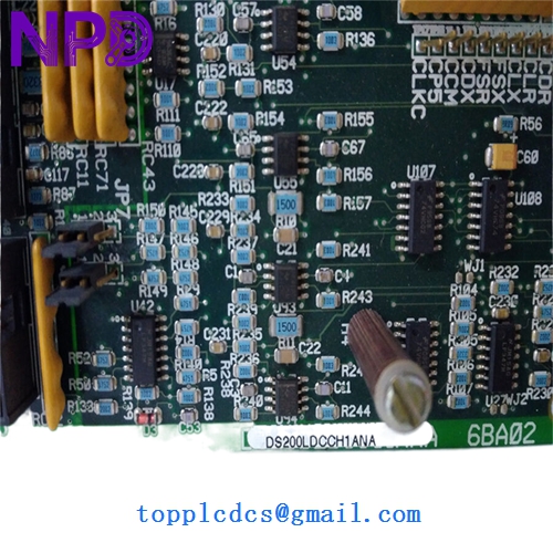
Description
- Model: DS200LDCCH1ANA
- Brand: General Electric (GE)
- Series: Mark V Speedtronic Control System
- Core Function: LAN Communication and Drive Control interface
- Type: LAN Display Control Cluster Board (LDCC)
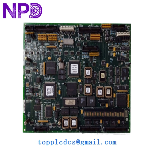
- Key Specs: 3 microprocessor architecture, ARCNET communication, 1x RS-232 port
- Microprocessors: Three onboard (16-bit) processors for high-speed logic
- Communication Protocol: ARCNET (Local Area Network)
- I/O Interface: RS-232 serial port for local programming/diagnostics
- Display Support: Connects to the local operator interface (STDR)
- Software Compatibility: Requires specific PROM (Programmable Read-Only Memory) chips
- Form Factor: Double-height VME-style board
- Power Consumption: Standard Mark V bus power (5 V DC / 12 V DC rails)
- Environmental Rating: 0 to 60°C operating temperature
GE DS200LDCCH1ANA
GE DS200LDCCH1ANA
Installation & Configuration Guide
Phase 1: Pre-Installation (Preparation: 15 minutes)
⚠️ Critical Safety: The Mark V system controls high-energy turbine equipment. Ensure the unit is in a “Safe” state (Stopped/Cooldown) before proceeding.
- Power down the control core (typically Core <R>, <S>, or <T>).
- Static Protection: You must wear a grounded ESD (Electrostatic Discharge) wrist strap. These boards are highly sensitive to static latent damage.
- Firmware Verification: Check the EPROM chips (the ones with labels like “U1”, “U2”) on your old board. New surplus boards often ship without PROMs or with different versions. You will likely need to migrate your original chips to the new board.
Phase 2: Removal (Step-by-Step)
- Labeling: Use a marker to label all ribbon cables connected to the front of the board (e.g., 2PL, 3PL).
- Cable Disconnection: Gently pull the ribbon connectors straight out. Do not pull by the wires.
- Extraction: Unscrew the retaining screws at the top and bottom of the faceplate. Use the board ejector tabs to slide the board out of the rack.
- PROM Migration: Use a chip extractor tool to move the software PROMs from the old board to the new one, ensuring the “notch” on the chip matches the socket orientation.
Phase 3: Installation & Power-On
- Alignment: Slide the DS200LDCCH1ANA into the guide rails until it seats firmly into the backplane.
- Secure: Tighten the faceplate screws and reconnect all labeled ribbon cables.
- Power-Up: Restore power to the core. Observe the alphanumeric display on the front of the board.
- Validation: Verify that the “Heartbeat” LED is pulsing and the board is communicating with the <I> processor or HMI.
Customer Cases & Industry Applications
Case 1: Sudden Communication Loss at a Power Plant A combined-cycle plant in Southeast Asia experienced a “Core Communication Failure” on their Mark V system. The DS200LDCCH1ANA in the <R> core had a processor fault. Since the plant lacked on-site buffer stock, they were 48 hours away from a total system trip. We dispatched a tested New Surplus board via priority airfreight. The plant bypassed a potential week-long outage, saving an estimated $450,000 in lost generation revenue.
Case 2: Proactive Lifecycle Management An industrial site running GE drives realized their LDCC boards were over 20 years old. Recognizing the increasing lead times for “Last-time-buy” parts, they ordered two DS200LDCCH1ANA units to keep as “insurance policies.” Six months later, a lightning strike fried an interface board; because the spare was already on-site, their downtime was limited to 45 minutes instead of weeks of searching the secondary market.
Frequently Asked Questions (FAQ)
Q: Does this board include the software PROMs? A: Usually, no. Most “New Surplus” boards are “blank” or have generic factory firmware. To ensure your turbine runs correctly, you must move the EPROM chips from your failed board to the new one. If your chips are damaged, we can sometimes assist with firmware duplication if you provide the version numbers.
Q: Why is there an “ANA” at the end of the part number? A: This refers to the revision level. “A” is the base, and “NA” indicates specific functional revisions. In my experience, GE boards are generally backward compatible, but you should always check if your system configuration files (CONFIG.DAT) require a specific revision.
Q: How do I know this isn’t a “pulled” or “used” board? A: We perform a “Live Test” using a GE Mark V test rack. We check for clean solder traces, lack of heat discoloration around the resistors, and original factory markings. Unlike “Refurbished” boards which may have replaced capacitors, our New Surplus units are in original, un-repaired condition.
Q: What is the most common cause of failure for the DS200LDCCH1ANA? A: Most often, it’s the electrolytic capacitors drying out after two decades of service, or failure of the ARCNET transceiver chip due to external surges. Replacing the whole board with a tested unit is significantly more reliable than attempting a component-level repair in the field.