Description
Product Core Brief
| Attribute | Detailed Information |
| Model | GE DS200PCCAG1ABB |
| Brand | General Electric (GE) |
| Series | Mark V Speedtronic / Innovation Series Drives |
| Core Function | Power Connect & SCR Control Interface |
| Product Type | Power Connect Card (PCCA) |
| Key Specs | Thyristor Gate Firing / Voltage Feedback / Snubber Circuitry |
Key Technical Specifications
- Gate Firing: Provides signals for up to six thyristors (SCRs) in a bridge configuration.
- Voltage Sensing: High-voltage feedback circuits for DC bus monitoring.
- Protection: Integrated snubber circuits to suppress voltage spikes and dv/dt transients.
- Connectivity: 10-pin and 24-pin ribbon cable connectors for communication with the main control board.
- Compatibility: Designed for use in GE Innovation Series Drives and Mark V Turbine Control Systems.
- Test Points: Accessible points for measuring gate pulse integrity and DC feedback levels.
- Revision: G1ABB (Indicates the specific hardware build and component configuration).
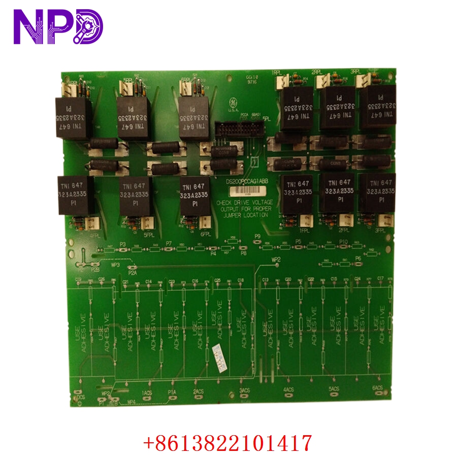
GE DS200PCCAG1ABB
GE DS200PCCAG1ABB
Application Scenarios & Pain Points
The DS200PCCAG1ABB serves as the “muscle-to-brain” interface in large-scale power conversion systems. While the control processor decides the timing, the PCCA card physically delivers the gate pulses to the heavy-duty SCRs (Silicon Controlled Rectifiers) and reports back the actual voltage status.
The Engineering Challenge:
In high-power environments like gas turbine starters or massive industrial drives, the PCCA card is exposed to significant electrical stress and thermal cycling. If a component in the firing circuit fails, the drive may suffer from “misfiring,” leading to harmonic distortion, mechanical vibration, or a complete “Phase Loss” trip. Because these systems are often central to plant operations (like a Main Feed Pump or a Turbine Starter), a failure here results in immediate downtime. Replacing the board with the exact revision is critical to ensure the gate pulse timing remains synchronized with the existing drive logic.
Typical Application Scenarios:
- Gas Turbine Control (Mark V)
Interfacing with the Load Commutated Inverter (LCI) during the start-up sequence of GE Frame 6, 7, or 9 turbines.
- Large AC/DC Drives
Controlling motor speed and torque in heavy industrial applications like paper mills or mining hoists.
- Excitation Systems
Managing the field current for large synchronous generators in power plants.
- Static Starter Systems
Providing the initial power conversion required to bring massive synchronous motors up to speed.
Case Study: The “Phase Loss” Mystery at a Peaker Plant
Background: A power peaking station used a GE Mark V system with an LCI starter. During a critical peak demand window, the turbine failed to start.
Problem: The system reported a “Phase Loss” and “SCR Fault” during the initial roll. Testing showed the SCRs were healthy, but the gate pulses were intermittent on Phase B. The DS200PCCAG1ABB card had a failing optocoupler in the firing circuit that would only glitch under load.
Solution: We provided a new surplus DS200PCCAG1ABB from our stock. Because the G1ABB revision was a perfect match, no calibration of the firing timing was required.
Result:
- Reliability Restored: The turbine successfully reached “Fire” speed on the first attempt after the swap.
- Revenue Saved: The plant met its grid commitment, avoiding heavy non-delivery penalties.
Compatible Replacement Models
The DS200 series has many variations; the PCCAG1 version is specific to its firing and feedback ratios.
| Original Model | Alternative Model | Compatibility Level | Notes |
| DS200PCCAG1ABB | DS200PCCAG1AAA | ⚠️ Backward Compatible | Earlier revision; ensure your software version supports it. |
| DS200PCCAG1ABB | DS200PCCAG2… | ❌ Incompatible | G2 versions have different voltage feedback scaling. |
| DS200PCCAG1ABB | DS215PCCAG1… | ❌ Hardware Mismatch | DS215 is the updated Mark VI style board. |
Troubleshooting Quick Reference
| Symptom | Possible Cause | Relevance | Quick Check | Action |
| Drive “Misfiring” / Vibration | Weak Gate Pulse | ✅ High | Use an oscilloscope to check the pulse width on the firing terminals. | If pulse is weak or missing, replace the PCCA card. |
| DC Bus Overvoltage Trip | Feedback Circuit Failure | ⚠️ Medium | Compare the HMI voltage reading with a manual DMM measurement. | If the PLC sees the wrong voltage, the feedback resistors are likely drifted. |
| Blown SCRs | Snubber Circuit Failure | ✅ High | Check for charred resistors or leaking capacitors on the PCCA board. | Replace card; a failed snubber will kill your expensive SCRs. |
| Comm Loss to Control Board | Ribbon Cable Damage | ⚠️ Medium | Inspect the pins on the J1/J2 connectors for oxidation or bends. | Clean pins or replace the ribbon cable before swapping the board. |
Field Engineer’s Insight:
When installing the DS200PCCAG1ABB, pay very close attention to the fiber optic and ribbon cable connections. These boards are often located in “Hot” sections of the drive cabinet. Over years of operation, the plastic clips on the connectors can become brittle. If you feel a connector is loose, secure it with a non-conductive tie-wrap. A vibration-induced loose connection on a gate firing card can cause a catastrophic “shoot-through” failure in your SCR bridge.
❗ Safety Warning: This board interfaces directly with high-voltage DC buses and AC lines. Ensure all capacitors are fully discharged before touching the board or the connected SCR bridge.
Do you need the specific jumper settings for the voltage feedback attenuation on this revision? Just let me know.