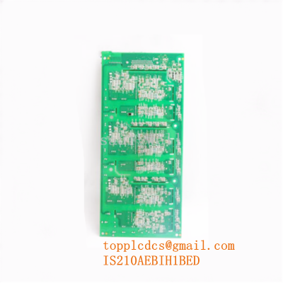
Description
- Model: DS200TCQCG1BKG
- Brand: General Electric (GE)
- Series: Speedtronic Mark V Turbine Control System
- Core Function: Processes analog inputs and outputs, scaling sensor signals for gas/steam turbine control loops
- Condition: Brand New Surplus (Original factory box with moisture barrier protection)
- Type: Analog I/O Expander Board (TCQC)
- Key Specs: Multi-channel inputs (RTD, thermocouples, 4-20 mA), onboard hardware jumpers, diagnostic LED matrix
-
- Input Capacity: Supports up to 15 standard analog input channels
- Output Capacity: 4 analog output loops for servo and valve control positioning
- Sensor Compatibility: Type J, K, T, E, and S thermocouples / 100 Ω Platinum RTDs
- Signal Processing Ranges: 4-20 mA current loops, ±10 V DC, and ±5 V DC voltage spans
- Hardware Configurator: Onboard multi-position berg jump pins and DIP switches
- Processor Node Interface: Dual-port ribbon connections matching , , and core structures
- A/D Conversion Resolution: 12-bit successive approximation analog-to-digital matrix
- Power Allocation: Consumes dedicated +5 V DC, +15 V DC, and -15 V DC lines via backplane
- Isolation Rating: 1,500 V AC galvanic protection across power processing pathways
- Environmental Rating: Ruggedized coating layer for high thermal/vibration turbine deck zones
GE DS200TCQCG1BKG
Installation & Configuration Guide
Phase 1: Pre-Installation (Estimated time: 15 minutes)
⚠️ Safety First:
- Secure strict authorization from the control room operator prior to taking the turbine control core offline.
- Ensure the turbine is completely shut down and placed on turning gear, or fully isolated with zero risk of accidental startup or fuel valve actuation.
- Isolate all power feeds entering the Mark V cabinet enclosure, including primary AC breakers and internal 125 V DC battery backing loops.
- Verify zero-voltage states on incoming terminals using a fluke multimeter before reaching into the card carrier chassis.
Tools and Materials:
- Grounded anti-static wrist strap connected to cabinet ground
- 3/16-inch nut driver and standard Phillips screwdriver
- High-resolution camera or smartphone for configuration mapping
- Keyed labeling markers for ribbon cable identification
Backup Actions:
- Execute an EEPROM backup configuration via the operator interface terminal before shutdown.
- Cross-reference current software I/O assignment files (CONFIG.DAT) to preserve customized sensor scaling coefficients.
Phase 2: Removal (Estimated time: 10 minutes)
- Secure your anti-static wrist strap to the unpainted metal earthing point inside the cabinet wall.
- Photograph the exact routing and orientation of all multi-conductor ribbon cables attached to the board surface.
- Unplug ribbon cables from connectors (such as 1PL, 2PL, 3PL) by squeezing the outer retaining clips and pulling straight back.
- Loosen the four corner nylon retaining screws attaching the card to the plastic standoffs.
- Withdraw the circuit board straight toward yourself to prevent scratching the backplane trace lines and store it immediately inside an ESD-shielded static pocket.
Phase 3: Installation (Estimated time: 15 minutes)
- Carefully remove the new card from its factory-sealed metal-out barrier packaging layer.
- Replicate every jumper pin location from the old module to the new board. Pay absolute attention to jumpers controlling thermocouple cold-junction compensation or 4-20 mA selection loops.
- Align the mounting holes over the chassis nylon support standoffs.
- Press down evenly on the module frame until it securely seats onto the alignment pins, then secure it using the retention screws.
- Reconnect all ribbon headers, ensuring the alignment keys match perfectly and side clips snap closed over the plugs.
Phase 4: Power-On & Initialization (Estimated time: 20 minutes)
- Re-check that zero loose screws, wire strands, or tools remain inside the live processing rack area.
- Re-energize the Mark V cabinet power circuits.
- Track the onboard diagnostic light-emitting diodes (LEDs); a successful initialization loop shows specific green sequence flashing with zero red error alerts.
- Open your engineering terminal workstation to verify core synchronization status across the voting controllers (, , ).
- Calibrate analog position feedback and servo loops through the tracking software interface to align zero/span parameters.
- Record the complete board identification matrix, including full alphanumeric revision suffixes, into the central master maintenance registry.
Customer Cases & Industry Applications
Case 1: Combined Cycle Power Plant Emergency Restabilization
Situation: A 150 MW combined cycle power facility located in the Gulf Coast region faced an unexpected unit trip during peak power dispatch hours. Diagnostic logs pointed to erratic fuel stroke reference values originating from the Mark V turbine controller panel, specifically tracing back to an analog expander card failure.
Task: Sourcing a replacement directly via traditional manufacturer streams introduced an estimated 14-week factory lead time variability. Sufferring extended downtime costs estimated at over $120,000 per production day made a long delay completely unacceptable.
Action: The operations manager contacted our logistics center to locate a ready stock module. We pulled the card from our climate-controlled warehouse, subjected it to strict physical and insulation trace inspections, and dispatched it via immediate hot-shot air courier delivery within hours.
Result: The component arrived on the turbine deck floor within 24 hours of the initial trip. Plant control technicians completed hardware swap out, replicated the necessary berg jumper pinning arrays, and re-synchronized the control cores. The turbine returned to active generation status shortly after, mitigating massive revenue losses and demonstrating the critical value of utilizing trusted surplus channels for aging assets.
Case 2: Steel Mill Co-Generation Plant Preventive Overhaul
Situation: An industrial manufacturing steel mill operating an internal steam turbine co-generation plant used older Mark V control panels that were nearing critical obsolescence milestones, with limited local buffer stock left on site.
Task: The plant’s capital allocation strategy aimed to extend control panel lifespan by another 10 years without absorbing the massive overhead of a complete modern system upgrade, which was quoted at over $650,000.
Action: Sourcing through our global distribution network allowed their asset group to execute a vendor consolidation strategy, securing multiple identical New Surplus boards to act as on-site insurance policies.
Result: The facility established a reliable spare parts pool, stabilizing operations and dropping their yearly stock-out risk to near zero while maintaining controlled capital holding expenses.
Frequently Asked Questions (FAQ)
Q1: What do the specific suffix letters “BKG” indicate on this board profile?
A: Suffix combinations in the GE tracking matrix represent exact revision levels. Specifically, G1 indicates the primary group revision architecture. The subsequent letters represent backward-compatible artwork and component updates. In my experience with these control panels, a “BKG” layout can directly replace older revision versions like “BFG” or “BGG,” but you must verify that all jumper options are hand-aligned to match your plant’s specific system wiring.
Q2: Is a full system software reload required after inserting this board?
A: Typically, no. The card processes physical analog IO signaling based on hardware jumper selections and parameters held in the core controller’s EEPROM. As long as you match the jumper positions exactly and replace the card with an identical functional model, the system will read configuration files automatically upon power up.
Q3: Why choose New Surplus over refurbished options for critical turbine systems?
A: Refurbished turbine parts carry higher failure risks due to heat-stressed capacitors, weakened solder joints, and aged optocouplers that face rapid degradation under high cabinet temperatures. Sourcing New Surplus units ensures you receive a component that has never seen operational thermal cycles, giving you maximum reliability and an operational life expectancy equal to original factory components.
Q4: How do we verify that the board we receive is genuinely un-used?
A: Every unit we dispatch remains sealed inside its high-grade ESD moisture barrier shield, marked with traceable serial barcodes. We are happy to provide detailed, high-resolution photos of the crisp board surface, clean gold edge traces, and component markings for your engineering team to inspect prior to packing and shipment.
Q5: What international shipping options are available for emergency shutdowns?
A: We provide global priority logistics coordination via DHL Express, FedEx Priority, and UPS Worldwide Saver. Most international power generation facilities and manufacturing hubs receive shipments within 3 to 5 business days. Full tracking, commercial customs invoices, and certificates of origin are managed directly by our shipping department to expedite local customs processing.