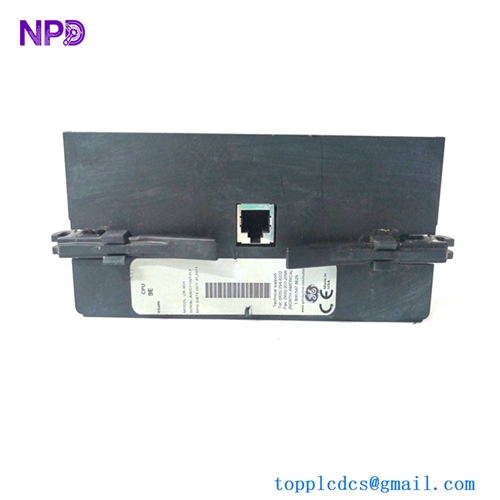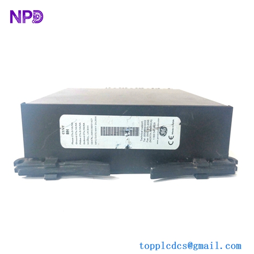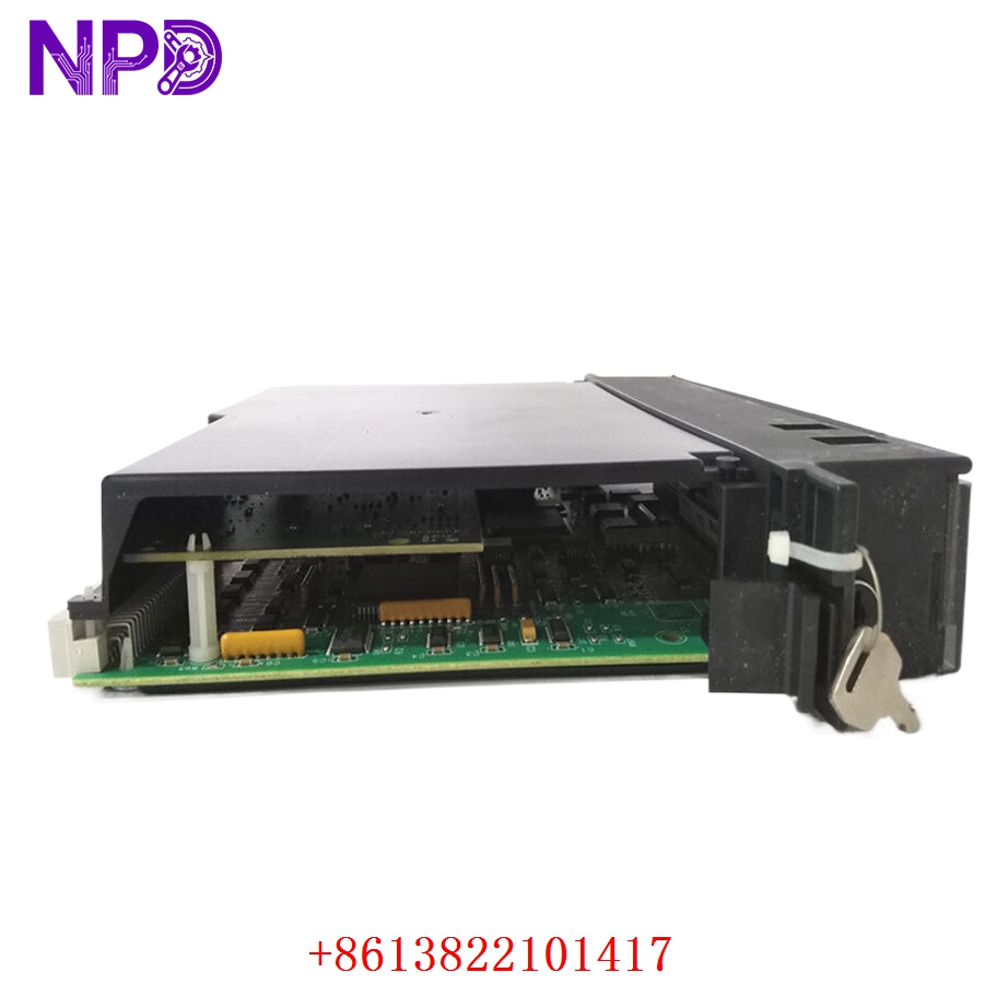

Description
- Model: IC697CPM790
- Brand: GE Fanuc / General Electric
- Series: Series 90-70 Programmable Logic Controller (PLC)
- Core Function: High-performance main controller module executing complex logic, floating-point math, and processing coordination for heavy industrial automation systems
- Condition: Brand New Surplus (Unused stock in pristine physical condition with factory static-barrier protection)
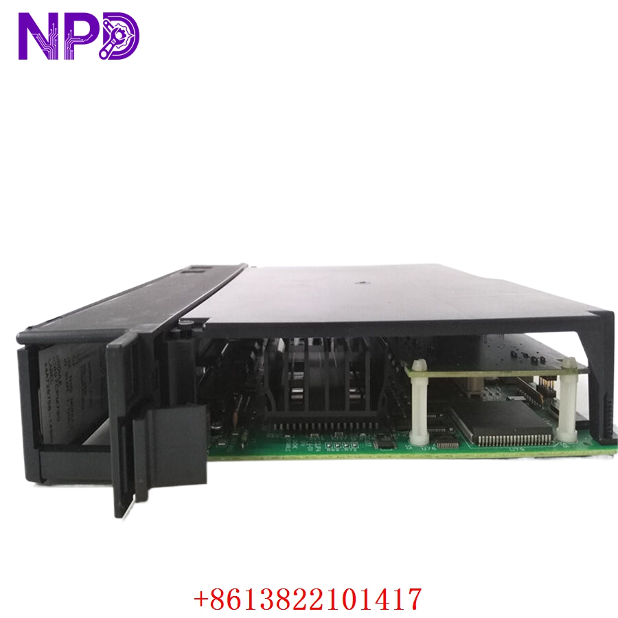
- Type: 32-Bit Central Processor Unit (CPU) with Floating Point Unit (FPU)
- Key Specs: 96 MHz processing speed, 512 Kbytes total battery-backed RAM, 512 Kbytes flash memory, 3-slot wide design
- Microprocessor: High-speed 32-bit internal architecture running at 96 MHz clock frequency
- Math Co-Processor: Integrated hardware Floating Point Unit (FPU) for fast execution of trigonometric, logarithmic, and advanced algorithmic processing
- Memory Capacity: 512 Kbytes of volatile, high-speed CMOS static RAM (system battery-backed) and 512 Kbytes of non-volatile Flash memory
- Boolean Execution Speed: 0.4 µs per standard boolean logic contact instruction
- I/O Capacity: Supports up to 8,192 discrete input channels, 8,192 discrete output channels, and up to 8,000 analog register loops
- Chassis Footprint: Requires three (3) adjacent standard module slots on the IC697 backplane rack
- Communications: Dedicated front-panel 15-pin D-shell serial port supporting SNP and SNPX protocol formats for programming and HMI linking
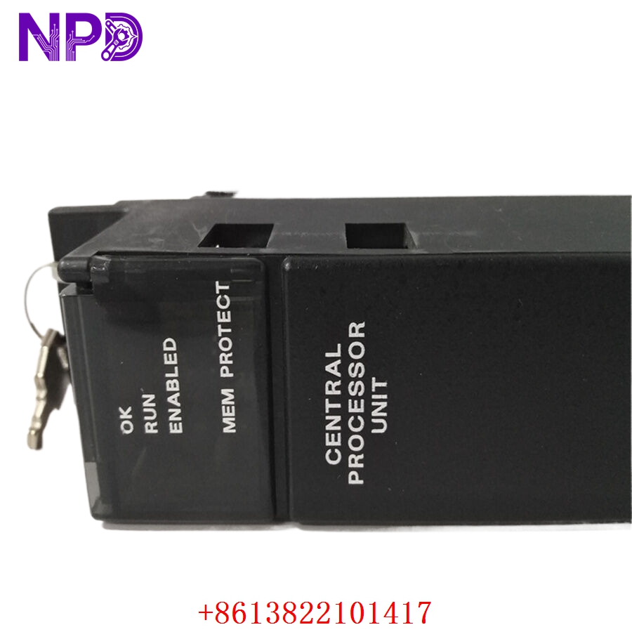
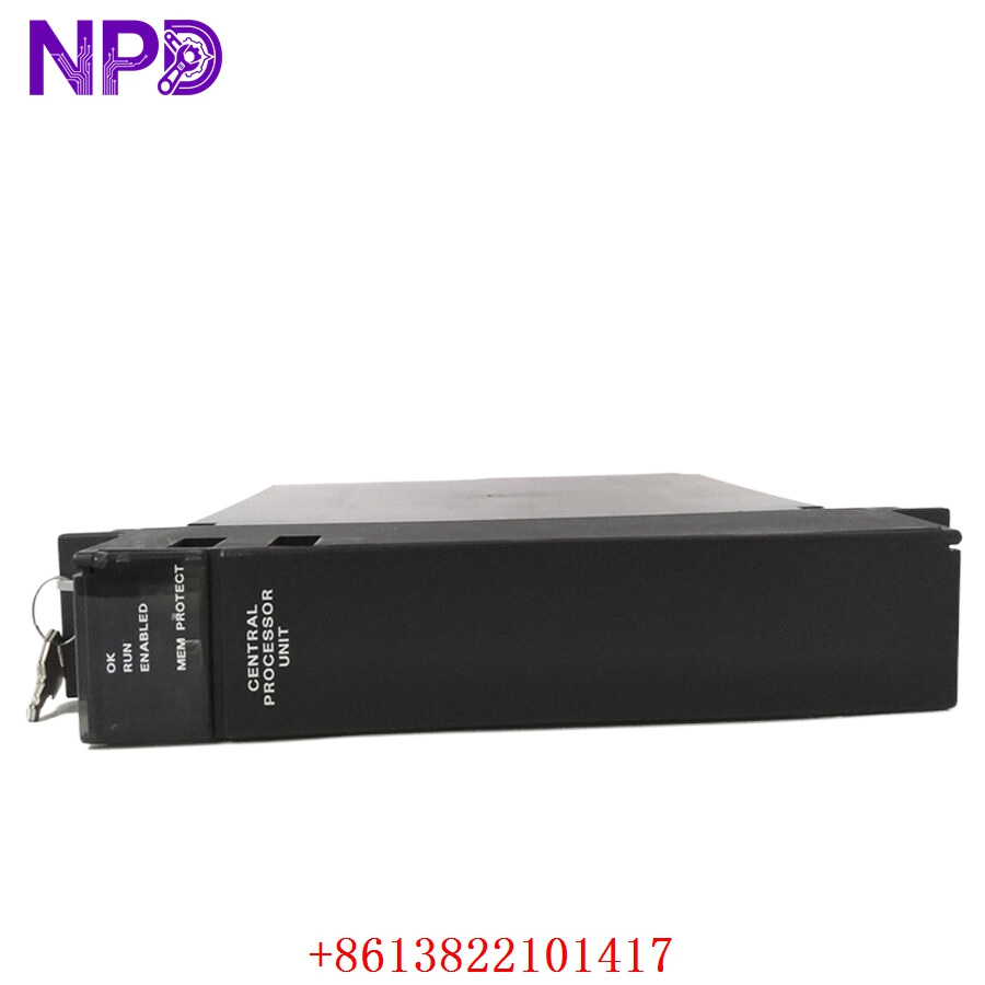
- Diagnostic Panel: Integrated multi-LED status cluster (OK, RUN, I/O ENABLE, BATTERY) plus a 3-position keyswitch for hardware operational override
- PCM / CMM Interface: Fully compatible with Programmable Coprocessor Modules and Communications Control Modules for advanced networking (Genius, Ethernet, Profibus)
- Current Draw: Takes roughly 3.1 Amps at +5V DC directly from the chassis backplane power supply bus
- Operating Temp: 0°C to +60°C (32°F to 140°F) surrounding ambient air profile
GE IC697CPM790
GE IC697CPM790
GE IC697CPM790
Installation & Configuration Guide
Phase 1: Pre-Installation (Estimated time: 15 minutes)
⚠️ Safety First:
- Get explicit authorization from operations management before changing or servicing an industrial core controller.
- Confirm the host assembly machinery is in a safe, fully de-energized, static state where unexpected valve movements or motor starts cannot happen.
- Turn off all main power disconnects running to the Series 90-70 rack rack housing.
- Verify zero voltage state inside the panel enclosure using an industrial voltage tester before touching internal terminal wiring blocks.
Tools and Materials:
- Grounded anti-static wrist strap with heavy-duty bonding clip
- Medium flat-blade screwdriver for card retention mechanisms
- Backup system battery (IC693ACC302 or equivalent) if configuring memory preservation parameters
- Programming laptop running Proficy Machine Edition or Logicmaster 90-70 software
Backup Actions:
- Upload and archive the current ladder logic, hardware configuration, and register variables from the active controller before removing it.
Phase 2: Removal (Estimated time: 5 minutes)
- Attach your anti-static strap clip securely to the bare metal frame grounding terminal of the control cabinet.
- Unplug any attached 15-pin programming interface serial cables from the lower front port of the card.
- Release the top and bottom mechanical board retention tabs built into the 3-slot module frame.
- Pull the module carefully forward out of its backplane alignment track, ensuring it remains straight to avoid flexing the long socket connectors.
- Place the removed CPU board inside a dedicated ESD protective pouch immediately.
Phase 3: Installation (Estimated time: 10 minutes)
- Extract the new IC697CPM790 module from its original static shield wrap.
- Set any required hardware option switches or battery connections located on the side panel of the board structure to match the old setup.
- Align the wide card frame with the guide rails of slots 2, 3, and 4 (standard positioning immediately next to the primary power supply module).
- Push the module firmly straight back into the rack until the dual-row pin assembly seats deeply into the backplane matrix.
- Snap the top and bottom mechanical latch mechanisms closed over the frame edge to lock the unit.
Phase 4: Power-On & Initialization (Estimated time: 20 minutes)
- Check that the rack layout is clear of any dropped hardware or loose wiring shards.
- Re-energize the main AC/DC power feeds to the Series 90-70 power supply unit.
- Check the faceplate diagnostic LEDs: the “OK” indicator should light up solid green, showing that the internal self-tests passed successfully.
- Connect your engineering laptop to the 15-pin SNP serial communication port.
- Download your archived hardware configurations and program software blocks into the CPU module memory space.
- Turn the front keyswitch position from STOP to RUN, confirm that the “RUN” and “I/O ENABLE” LEDs light up solid green, and verify that field operations are tracking accurately across all networks.
Customer Cases & Industry Applications
Case 1: Paper Mill Pulp Digester Process Life Extension
Situation: An operational pulp and paper manufacturing plant in the Midwest used an extensive GE Fanuc Series 90-70 control architecture to run its primary wood pulp digester system. During an un-planned maintenance cycle, an electrical surge damaged the main processor board, halting all cooking loops.
Task: The plant faced an immediate production freeze on high-margin paper stock lines. Factory automation channels quoted an 8-to-12 week fulfillment delay because the 90-70 series is an older, obsolete platform, while a complete system modernization would require over $200,000 in hardware and programming costs.
Action: The facility engineering team contacted our regional warehouse network to source an immediate replacement. We pulled an un-used, brand-new surplus IC697CPM790 processor module from our stock, ran it through physical trace inspections, and sent it via priority air courier delivery within hours.
Result: The component arrived at the mill door within 24 hours of the initial failure. The plant electrician installed the board, loaded the original Logicmaster configuration file, and brought the digester back online. This avoided massive downtime costs and showed the value of utilizing clean surplus inventory to keep critical legacy assets running smoothly.
Case 2: Municipal Water Treatment Plant Backup Strategy
Situation: A regional water authority managing a network of clean water pumping stations used robust Series 90-70 controllers for their high I/O density and reliability, but lacked on-site backup hardware for their main processors.
Task: The plant’s engineering team needed to find a reliable source for a replacement CPU to minimize long-term operational risks without exceeding their tight municipal budget.
Action: We supplied a verified New Surplus IC697CPM790 card, complete with a 12-month warranty, to serve as their primary on-site spare insurance policy.
Result: The water treatment facility secured their critical process loop infrastructure, meeting safety regulations and avoiding expensive, un-planned modernization spending.
Frequently Asked Questions (FAQ)
Q1: Is the IC697CPM790 backward compatible with applications built for older CPM770 or CPM780 processors? A: Yes. The CPM790 runs on the same underlying 90-70 hardware platform and can interpret code written for older CPUs like the CPM770 or CPM780. However, you will need to open your original software project file (Logicmaster or Proficy) and change the target CPU type in the hardware configuration profile before downloading the code to the new module.
Q2: How does the integrated Floating Point Unit benefit my system compared to a standard CPU? A: The onboard hardware FPU handles complex mathematical equations (such as PID loop algorithms, scaling calculations, and trigonometric formulas) directly on dedicated hardware. This prevents the main microprocessor from having to run software-based math emulations, significantly speeding up overall program scan times in complex applications.
Q3: How are user programs and configurations preserved during a total power failure? A: The IC697CPM790 uses a combination of high-speed volatile RAM and non-volatile Flash memory. To keep your running data and variables intact in the RAM space when the rack is powered down, you must connect a standard lithium backup battery plug to the port on the CPU module housing. Alternatively, you can write the master logic configuration directly to the Flash memory area for long-term safety storage.
Q4: Which software versions do I need to configure and program this processor? A: This module can be programmed using older legacy software like Logicmaster 90-70 (version 7.0 or higher) or modern setups like Emerson/GE Proficy Machine Edition. Connections are typically made using a standard RS-232 to RS-485 SNP communication converter cable attached to the 15-pin front connector port.
Q5: What steps are taken to make sure this legacy surplus hardware arrives in perfect condition? A: Every IC697 processor module we handle is stored inside a climate-controlled warehouse environment. When an order is placed, the card is packed inside a high-grade static-shield barrier bag, cushioned with multi-layer shock protection foam, and placed into a thick shipping box. We ship daily using express couriers like DHL, FedEx, and UPS to ensure safe, traceable, and fast delivery to your site.