Description
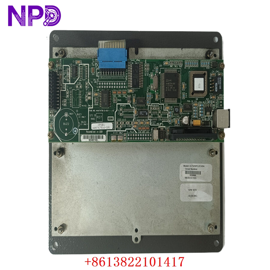
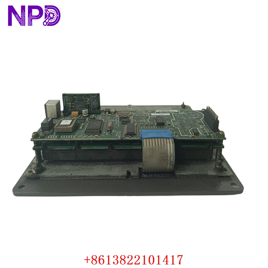
- Model: GE IC752SPL013-BA (Associated Board Part Number: 151X1207BA10SA01)
- Brand: General Electric (USA)
- Series: EX2100 Excitation Control / Innovation Series Drive
- Core Function: Local keypad operation and display interface unit for excitation systems, New Surplus / Rebuilt condition
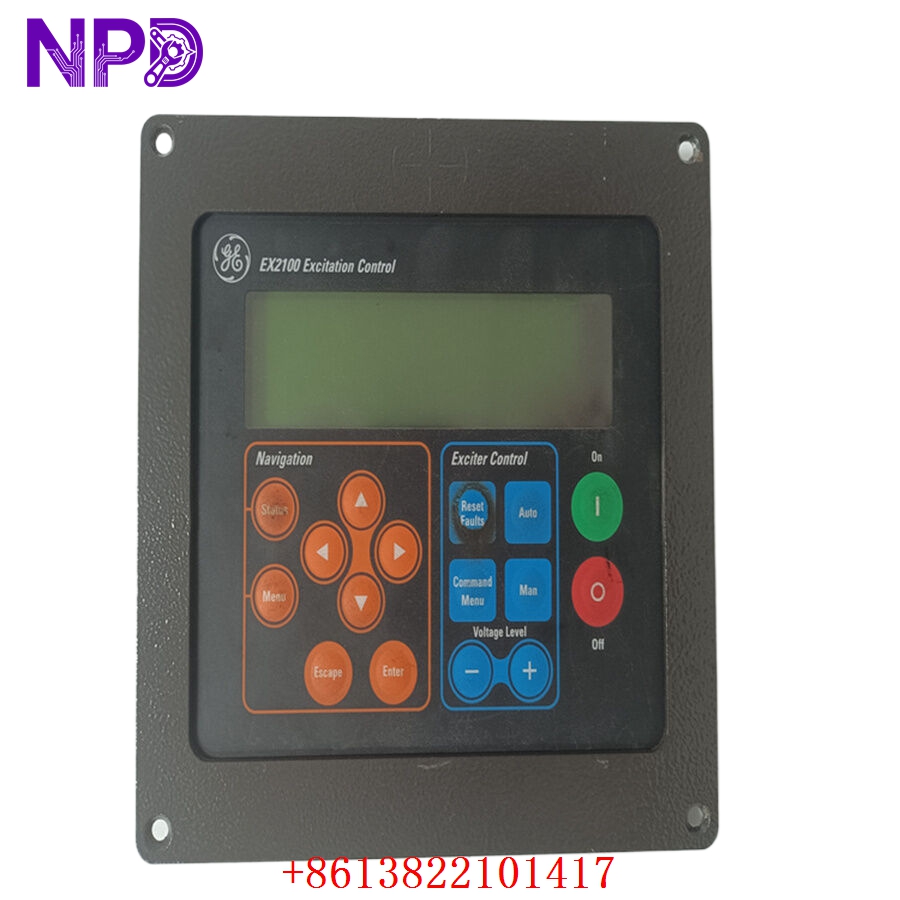
- Type: Excitation Control Interface Panel (ECP) / Keypad Assembly
- Key Specs: 24 V DC internal logic input, 12-button navigation matrix, 16-character alphanumeric monochrome LCD
- Input Power Requirements: 24 V DC backplane derived power
- Display Configuration: 16-character backlit alphanumeric LCD matrix
- Operator Input Interface: 12-key industrial membrane keypad dome switch array
- Housing Form Factor: Flush-mount, integrated VME rack frame bezel design
- Interface Protocol: High-speed synchronous serial interface linking directly to the VME control card rack
- Gasket Material: Oil-resistant integrated neoprene front panel seal
- Enclosure Rating: Front bezel meets IP54 equivalent standards when flush-mounted in a matching cutout
- Operating Temperature: -40 °C to +70 °C
- Storage Temperature Range: -55 °C to +85 °C
- Approximate Net Weight: 3.0 kg (including rugged mounting plate assembly)
GE IC752SPL013-BA
GE IC752SPL013-BA
GE IC752SPL013-BA
Application Scenarios & Pain Points
When a gas turbine or utility generator is online, the excitation system is the heart that keeps the grid synchronized. If the local operator panel goes blank or the membrane buttons wear out from years of field use, technicians lose the ability to perform manual tuning, view step response values, or clear localized fault locks from the panel front. This particular keypad unit is an essential diagnostic window for vintage EX2100 installations. When it breaks, field engineers are blind on the turbine deck, turning standard maintenance routines into high-risk operations.
Typical Application Scenarios
- Power Generation – Utility-Scale Generator Excitation
Acts as the localized interface for the EX2100 control rack, managing voltage regulations, reactive power setpoints, and governor system co-processing.
- Heavy Industrial Drives – Synchronous Motor Control
Provides a manual navigation layout for commissioning massive horsepower compressors or rolling mills in steel plants utilizing Innovation Series drive setups.
- Combined Cycle Power Plants – Peaking Unit Maintenance
Installed inside the generator control compartment to enable instant status readouts during automated turbine startups.
Real-World Field Case: Restoring Local Control on an Utility Generator
Background: During a scheduled hot-restart sequence at a thermal power plant in eastern China, the plant floor team needed to manually step up the base voltage regulator on the auxiliary generator package.
The Problem: The aging plastic dome switches beneath the navigation overlay had cracked over a decade of continuous exposure to cabinet heat. The “Enter” and “Arrow Up” inputs refused to register commands. The automated sequencing worked, but local engineers could not manually tweak parameters or acknowledge a secondary cooling system warning indicator directly from the rack layout. Waiting for a complete control architecture migration was a non-starter.
The Solution: The maintenance coordinator contacted our depot. We retrieved a clean, warehouse-stored unit, ran a functional button-trace continuity sweep on our simulated test bench, verified the integrated display contrast, and dispatched the assembly through an overnight hot-shot delivery courier.
The Result:
- Delivery turnaround: Received at the plant main gate 18 hours after order placement.
- Resolution: The local instrument team unbolted the failed panel, transferred the backplane connection ribbon, and restored local diagnostic capabilities before the unit was synchronized back to the high-voltage network.
Compatible Replacement Models
Be very careful when reviewing suffix variations for this specific family. The differences between revisions dictate whether you can directly slide the unit back onto the frame or if you are looking at a mismatched wiring loom.
- IC752SPL013-BB → Direct Drop-in Replacement
- Differences: This is a later manufacturing lot variation. It shares the identical ribbon connection scheme and identical cut-out dimensions. It features slightly upgraded tactile feedback on the front membrane array.
- Action: No hardware alterations or software re-mapping steps are required.
- IC752SPL013-AA → Software / Mechanical Check Required
- Differences: This represents the early-generation release. It is fully functional from a logic standpoint, but ensure the firmware version running on your main VME core module handles older hardware revisions gracefully without triggering a minor device mismatch flag.
- Cost impact: Generally runs about 10% lower in current market value if found in surplus stocks.
Troubleshooting Quick Reference
When things act up on the turbine panel, look up this tabular chart to pinpoint where the breakdown is actually occurring before you start pulling parts out of the rack enclosure.
| Observation | Probable Origin | Backplane Relevancy | Local Diagnostic Sweep | Immediate On-Site Fix |
| Backlight is visible but text line is missing | Contrast trimmer shifted or internal logic lockup | ⚠️ Medium | Cycle control power to the EX2100 VME rack slot module. Check for loose pins on the ribbon bus. | Carefully adjust the small potentiometer trace on the rear board using an insulated adjustment tool to dial back the screen bias. |
| Certain keypad inputs fail to execute actions | Cracked trace lines or ribbon connector degradation | ✅ High | Power down the panel. Use a precision digital multimeter to run a pin-to-switch resistance test across the ribbon path. | Replace the membrane frame assembly or swap the entire unit if internal copper tracks have oxidized. |
| Display shows garbled characters or random blocks | Communication noise or loose serial ribbon interface | ⚠️ Medium | Check if the high-voltage excitation cables are routed near the low-voltage communication paths inside the cabinet panel door. | Re-seat the internal communication cable on the rear header. Ensure the ribbon shield line is grounded flat against the chassis frame. |
| Panel stays completely dead while VME rack is live | Loss of 24 V DC supply feed on the backplane loop | ❌ Low | Test incoming power rails at the distribution block. Check for a blown inline fuse on the door branch. | Replace the blown cabinet fuse or swap out the dedicated auxiliary power supply board if the 24 V rail is flat. |
❗ WIRING AND HANDING WARNING: Do not hot-unplug the rear ribbon cable connection while the excitation control system is energized. Doing so can cause a momentary voltage sag on the internal VME communication bus, which can trip the master controller card and trigger a complete emergency shutdown event on the running generator unit.
If your field technicians are tracking an erratic error code or need a physical validation video of our ready-to-ship stock blocks performing standard keypad traces before making a buying decision, let us know. We can record a bench test run against our current stock units within two hours.