
Description
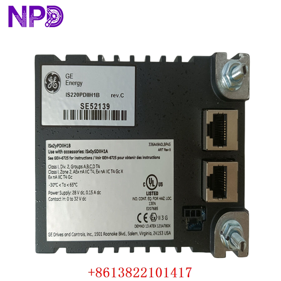
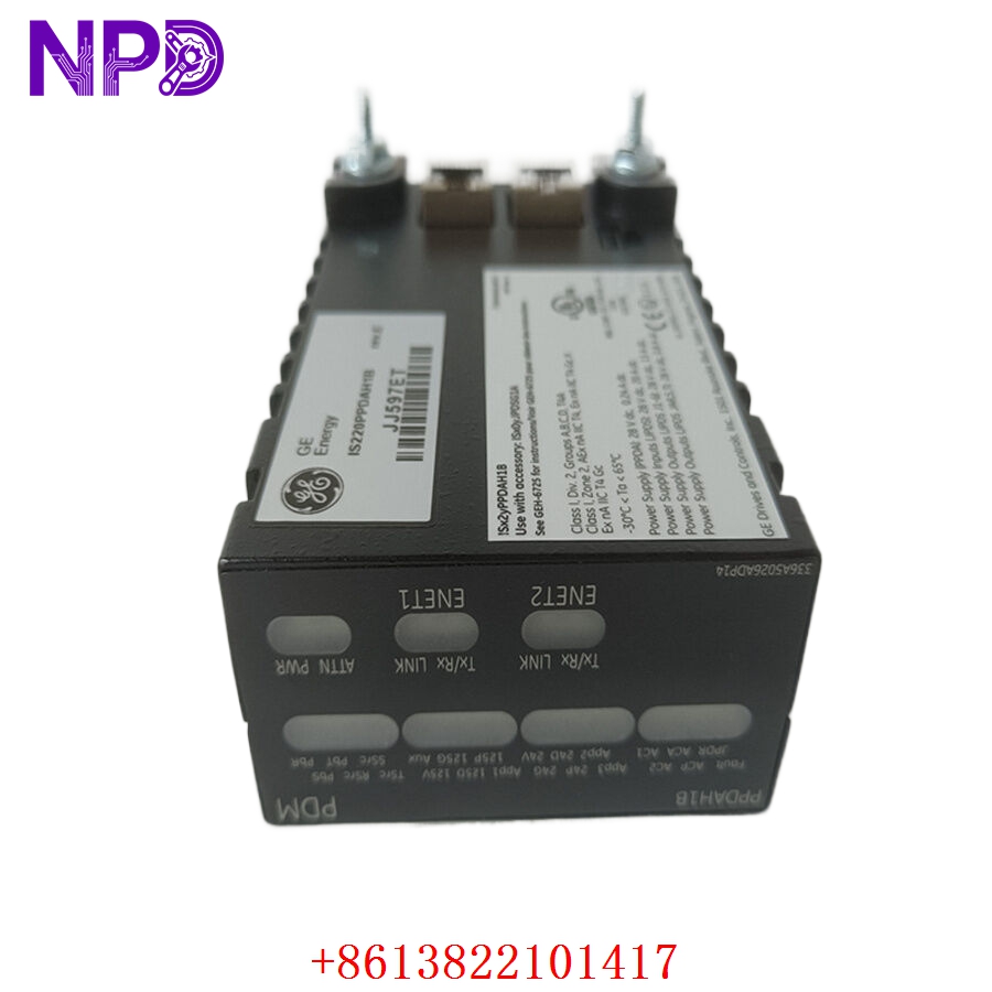
- Model: GE IS220PPDAH1B (Commonly associated with assembly number 336A5026ADP14)
- Brand: General Electric (GE Vernova)
- Series: Mark VIe Control System
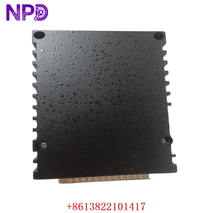
- Core Function: Serves as a Power Distribution Pack (PPD) responsible for managing, monitoring, and distributing DC power within the Mark VIe I/O rack, Original New Surplus condition
- Type: Power Distribution I/O Pack
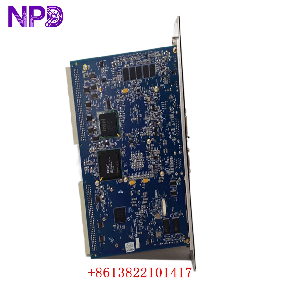
- Key Specs: Input voltage monitoring, output power distribution, and health diagnostic reporting
- Function: Monitors the health and status of the 24 V DC power buses and distributes them to the I/O packs and processors in the rack.
- Diagnostics: Provides real-time health data (voltage levels, power status) to the Mark VIe controller.
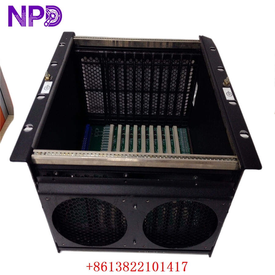
- Connectivity: Plugs directly into the Mark VIe I/O terminal block/base to receive input power and distribute it across the rack.
- Reliability: Designed for high-availability environments with redundant power monitoring capabilities.
- Operating Temperature: -30 °C to +65 °C.

GE IS220PPDAH1B 336A5026ADP14
GE IS220PPDAH1B 336A5026ADP14
GE IS220PPDAH1B 336A5026ADP14

GE IS220PPDAH1B 336A5026ADP14
Part 4: Installation & Configuration Guide
Phase 1: Pre-Installation (Estimated Time: 15 minutes)
⚠️ Safety First:
- Ensure the Mark VIe cabinet is in a safe maintenance state.
- Use an ESD-safe wrist strap to prevent static damage to the sensitive power electronics.
- Verify that the power inputs to the specific I/O terminal block are isolated before attempting to remove or install a pack.
Tool Preparation:
- Phillips screwdriver
- ESD wrist strap
- Multimeter for verifying power bus voltages
Phase 2: Removal & Installation (Estimated Time: 20 minutes)
- Identify: Locate the IS220PPDAH1B module in the Mark VIe rack.
- Remove: Release the side-locking tabs on the I/O pack. Pull the unit straight out of the terminal block base.
- Inspect: Check the terminal block base for any debris or pin damage.
- Install: Align the new pack with the guide rails on the terminal block. Push it firmly into place until the locking tabs click.
- Verify: Ensure the unit is flush and secure.
Phase 3: Verification (Estimated Time: 15 minutes)
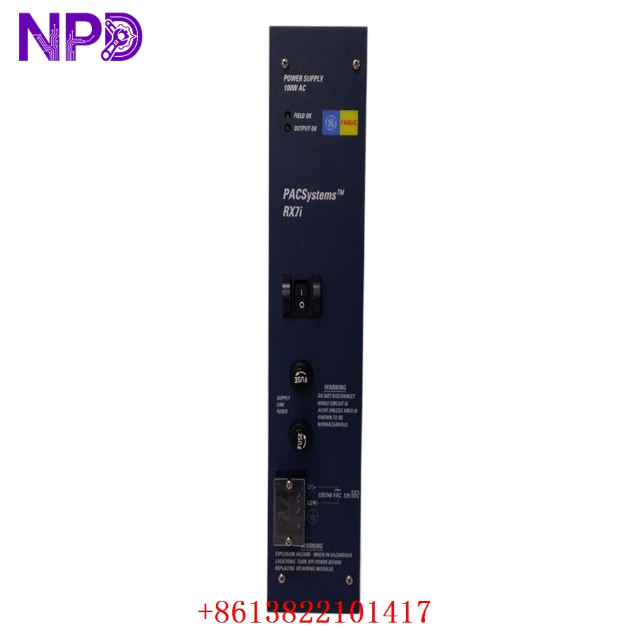
- Restore Power: Energize the DC power supply to the rack.
- LED Check: Observe the faceplate LEDs. A healthy pack should show a steady green status indicator (Run/Power).
- Software Sync: Access the ToolboxST configuration software to ensure the module is communicating and that power levels are correctly reported in the diagnostic screens.
Part 5: Industry Applications
Case 1: Power System Reliability
A power plant operator faced intermittent power fluctuations in their control rack. Replacing the aging PPD module with a new surplus IS220PPDAH1B ensured consistent power distribution and reliable diagnostic reporting to the controller, eliminating the nuisance alarms that were previously caused by the failing module.
Case 2: System Expansion
During a system upgrade, an engineering team required additional power distribution capacity to support new I/O modules added to their Mark VIe cabinet. The reliability of these new surplus units provided the stable 24V DC environment necessary for the expanded I/O architecture.
Part 6: Frequently Asked Questions (FAQ)
Q1: What is the relationship between IS220PPDAH1B and 336A5026ADP14?
A: The IS220PPDAH1B is the model name for the module, while 336A5026ADP14 is the specific assembly part number. Both identify the same hardware; they are used interchangeably to ensure you are receiving the correct revision and functional build of the Power Distribution Pack.
Q2: Can this pack be replaced while the system is running?
A: The Mark VIe I/O packs are designed for “hot-swapping” in many configurations, but it is highly recommended to follow your site’s specific safety procedures and check the ControlST diagnostic status before removing any module under load.
Q3: How do I know if the PPD is failing?
A: Common indicators include diagnostic alerts in ToolboxST regarding “Power Supply Faults” or “Bus Voltage Low,” as well as visual indicators on the module faceplate showing red fault LEDs.