Description
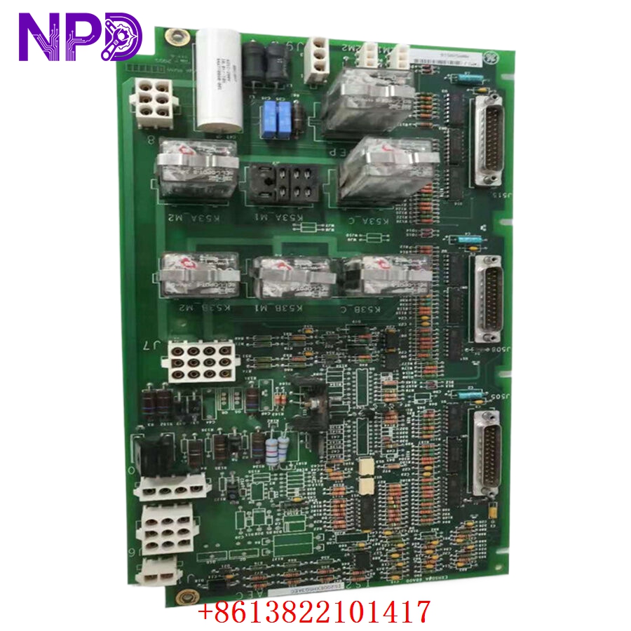
- Model: IS200EXHSG3AEC (Internal Reference / Manufacturing Code: MRP528516)
- Brand: General Electric (GE)
- Series: EX2100 Excitation Control System (Speedtronic Turbine Management family)
- Core Function: Acts as a high-speed relay driver and static exciter terminal board, managing DC contactors and pilot relays required for generator field flashing, de-excitation, and crowbar safety loops.
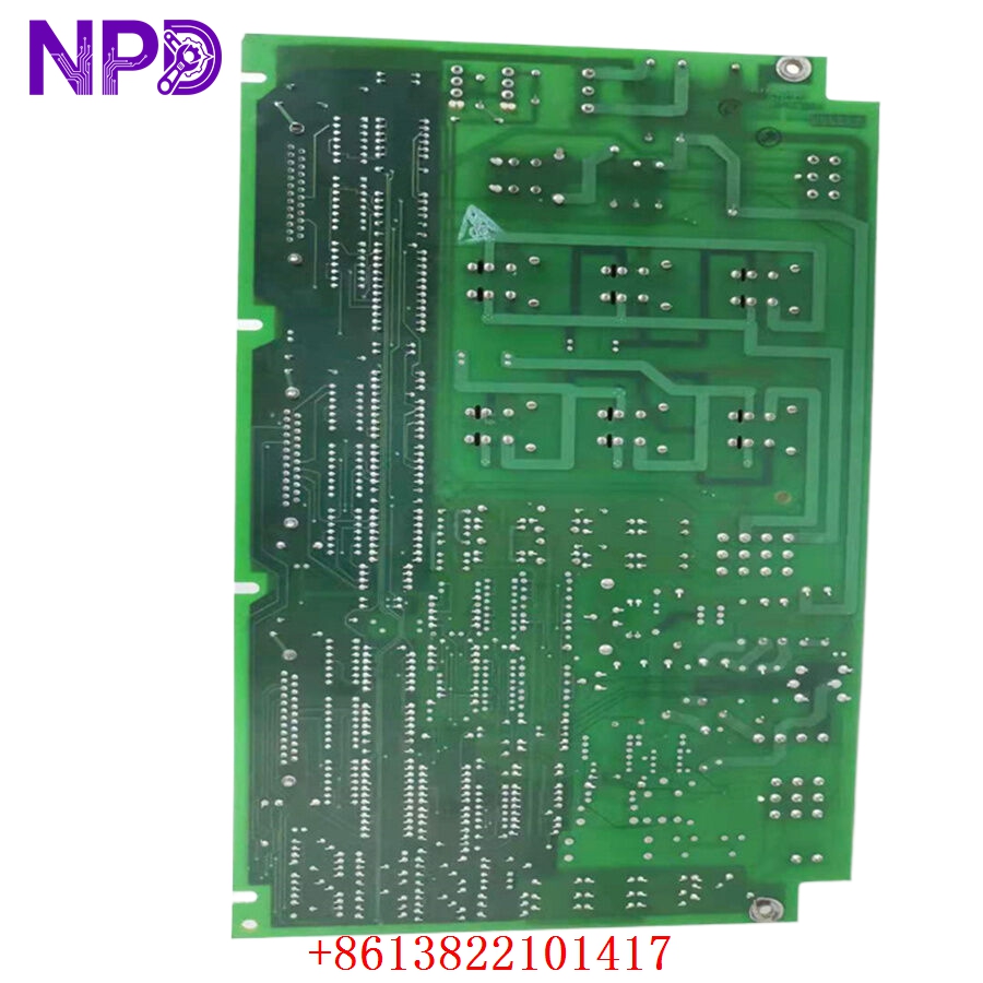
- Condition: Brand New Surplus (Prisine physical condition, kept in warehouse storage with anti-static shielding)
- Type: Static Exciter High-Speed Relay Driver Terminal Board (EXHS)
- Key Specs: 3 x 25-pin D-shell connectors (J505, J508, J515), 7 integrated onboard relays, 70V DC auxiliary contact wetting, conformal coated PCB structure.
- Functional Acronym: EXHS (Exciter High-Speed Relay Driver Board)
- Group Variation: G3 (Configured for high-current applications and enhanced Triple Modular Redundant architecture)
- Artwork Revision Suffix: AEC (Features ‘C’ level physical layout adjustments with premium protective circuit layers)
- Core Relay Architecture: Includes 7 distinct onboard relays; K41 (M1, M2, C) regulates the close function contactors, K53A/K53B handle flashing pilot relays, and KDEP manages the single de-excitation pilot loop.
- System Connectivity:
- J505: Connects directly to the M1 Excitation Monitoring and Instrumentation Output (EMIO) board.
- J508: Connects to the M2 EMIO board block.
- J515: Connects to the C EMIO controller (note: J515 does not route de-excitation or crowbar signaling paths).
- Power Allocation Ratings:
- Relay Coils: Powered via terminal J9, pulling a nominal voltage of 125V DC (operational threshold parameters span 100V DC minimum to 140V DC maximum).
- Relay Contacts: Powered out of the exciter cabinet grid at a nominal 24V DC.
- Wetting Voltage: Plugs J12M1 and J12M2 supply a dedicated 70V DC line sourced from M1 and M2 supplies to ensure stable auxiliary contact wetting.
- Relay Break Capacity:
- Resistive Load: Supports up to 2 A rating at 28V DC.
- Inductive Load: Manages up to 1 A rating at 28V DC for transient durations lower than 0.007 seconds (L/R constant parameters).
- Signal Condition Matrix: Conditions and safely shifts de-excitation status metrics from the Exciter De-Excitation Board (EDEX) and crowbar protective safety indicators from the De-Excitation Control Board (EXDE) directly over to the main EMIO processing blocks.
- Surge Suppression: Coil transient suppression is handled through external cabinet components (zero direct suppression circuitry located on the EXHS raw board area).
GE MRP528516 IS200EXHSG3AEC
GE MRP528516 IS200EXHSG3AEC
Installation & Configuration Guide
Phase 1: Pre-Installation (Estimated time: 15 minutes)
⚠️ Safety First:
- Request explicit authorization from the primary power generation control desk before decoupling active turbine excitation loops.
- Ensure the generator is completely at a standstill, fully isolated from grid synchronization, and all residual stored field energy has safely discharged.
- Deactivate and lock out the core excitation system power supply, verifying that all input circuit breakers feeding the cabinet housing are tagged out.
- Test internal cabinet terminal nodes using a certified digital multimeter to guarantee zero voltage remains present across high-current processing lanes.
Tools and Materials:
- Fully grounded ESD-shielded wrist band with a solid cabinet frame grounding clamp
- Precision Phillips and flat-head screwdrivers
- Core cable identification labels or wire markers
- Digital multimeter
Backup Actions:
- Carefully cross-reference the current system hardware inventory and parameters inside the ToolboxST programming terminal to match revision profiles perfectly.
Phase 2: Removal (Estimated time: 10 minutes)
- Secure your anti-static wrist strap directly to an unpainted, bare grounding spot on the enclosure panel frame.
- Label each multi-conductor connector and ribbon cable line with its matching board location name (such as J505, J508, J515, J12M1) to make re-installation straightforward.
- Disconnect the three 25-pin D-shell connectors by loosening the outer manual mounting thumb screws, then pull straight back from the board interface.
- Unplug all multi-position power and contact wetting connectors from their respective headers.
- Loosen the physical mounting retention fasteners holding the PCB plate assembly to the interior backplane rack, then safely slide the board out into a static shielding pocket.
Phase 3: Installation (Estimated time: 15 minutes)
- Carefully unpack the new IS200EXHSG3AEC module from its metal-out static shield layer.
- Confirm that the group variation (G3) matches the exact classification profile of the hardware unit you just removed.
- Position the card frame securely onto the dedicated chassis panel mounting holes.
- Tighten the board retention fasteners evenly across the substrate frame to ground the drilled conductive ring edges securely against the chassis bracket.
- Re-seat all plug connectors and screw the 25-pin D-shell multi-cable lines back into interfaces J505, J508, and J515, locking the thumb grips down firmly to prevent vibratory signal loose-contact errors.
Phase 4: Power-On & Initialization (Estimated time: 20 minutes)
- Double-check that all tools, loose wires, and structural debris are completely cleared from the active circuit card deck.
- Restore main line operating power to the EX2100 excitation controller cabinet.
- Monitor system initialization data logs on the operator terminal, checking that the redundant EMIO channels recognize the new high-speed relay driver without reporting feedback connection faults.
- Execute an operational sequence test on the de-excitation and field flashing pilot relay networks to verify that auxiliary contact feedback is registering accurately at 70V DC.
- Update your control room station log registry with the exact serial data matrix of the newly installed board assembly.
Customer Cases & Industry Applications
Case 1: Gas Turbine Power Plant Peak Load Excitation Fix
Situation: A peak-load gas turbine generation station running a GE EX2100 excitation control rig experienced recurring field flashing synchronization faults during a high-demand grid support startup sequence. Diagnostics isolated the issue to intermittent contact feedback failures on the old high-speed relay driver interface, creating an immediate risk of a startup failure during high-revenue operating windows.
Task: Sourcing an upgrade replacement directly from factory production channels involved extended lead times that would have stretched through the peak season. The plant’s asset manager needed to find an immediate replacement to maintain their quick-start grid compliance status.
Action: The maintenance supervisor contacted our logistics center to locate the part. We immediately verified the availability of a brand-new surplus IS200EXHSG3AEC (MRP528516) card from our stock, verified its G3 configuration layout, and shipped it out via priority air courier within hours.
Result: The board reached the site the following morning. Field technicians completed the physical installation, attached the EMIO tracking lines, and initiated a successful field flashing test run. The gas turbine recovered its quick-start reliability immediately, preventing costly failure-to-start penalties and keeping their critical generation asset ready for peak demand.
Case 2: Industrial Paper Mill Co-Gen Steam Turbine Overhaul
Situation: An industrial manufacturing paper mill running its own internal steam turbine co-generation unit planned a major preventive shutdown maintenance cycle to update its legacy excitation system components.
Task: The engineering division needed to update their critical safety boards, specifically the field crowbar and de-excitation status drivers, to modern, reliable component standards to avoid unexpected future shutdowns.
Action: We supplied a verified, un-used surplus IS200EXHSG3AEC board featuring a high-grade conformal protective coating to help shield the electronics from the mill’s high-humidity environment.
Result: The mill successfully integrated the new driver board into their system during the scheduled outage. This proactive replacement dropped their unplanned shutdown risks to near zero, providing long-term reliability while keeping overhead costs well within budget.
Frequently Asked Questions (FAQ)
Q1: What structural differences exist between the G3 variation and older G1/G2 versions of this board?
A: The Group 3 (G3) variation is designed to support higher redundancy control structures (such as Triple Modular Redundant configurations linking to M1, M2, and C cores simultaneously) and features robust trace path enhancements optimized for high-current generator excitation applications. You should always ensure that you replace like-for-like group models when servicing your excitation cabinet layout.
Q2: What role does the 70V DC line play across plugs J12M1 and J12M2?
A: This dedicated 70V DC line is pulled from the M1 and M2 power source paths specifically for auxiliary contact wetting. This configuration provides a clean, stable voltage supply that clears away light surface oxidation on the relay contact faces, helping to guarantee highly accurate position and status feedback signaling over years of continuous operation.
Q3: Can an “AEC” suffix revision replace an older “AEA” or “AEB” layout?
A: Yes. In GE’s design architecture, the “C” revision in the “AEC” suffix represents a physical artwork revision layer. It introduces aesthetic or minor layout updates that maintain complete backward functional compatibility with earlier versions. This means you can drop it directly into an existing slot that used a lower revision level without needing to modify your software configuration.
Q4: Why does the J515 connector interface omit de-excitation and crowbar status signaling?
A: Under the EX2100 control strategy, the J515 port is assigned to link directly with the ‘C’ (Core/Simplex) monitoring node. Because primary safety emergency trip loops (such as field crowbar firing and high-speed de-excitation) are managed directly by the main ‘M1’ and ‘M2’ active voting controllers, those specific high-risk signals are routed exclusively through connectors J505 and J508.
Q5: How are these high-precision EX2100 control boards prepared for long-distance transport?
A: Every component we ship is enclosed in an industry-standard anti-static ESD shield pouch, packed with multi-layer cushioning foam, and placed inside a heavy-duty shipping box. We coordinate daily priority shipments through global couriers like DHL and FedEx, ensuring fast, safe, and fully traceable delivery to your facility.