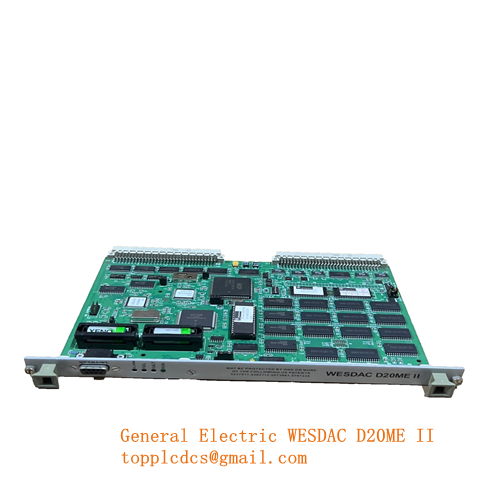
Description
- Model: VMIVME-4116
- Brand: GE Fanuc / VME Microsystems International (VMIC) / Abaco Systems
- Series: VMEbus Analog Output Series
- Core Function: High-resolution digital-to-analog conversion for precision control loops.
- Product Type: 8-Channel, 16-Bit Analog Output Board
- Key Specs: 16-Bit Resolution 8 Independent Channels VMEbus Compatible
- Number of Channels: 8 independent analog output channels.
- Resolution: 16-bit (high precision).
- Output Ranges: Jumper-selectable (typically ±10V, ±5V, 0 to 10V, or 0 to 5V).
- Settling Time: Approx. 10 µs to 0.01% of full-scale step.
- Data Transfer: A16/A24/A32 address space; D16/D32 data transfer.
- Accuracy: Highly stable with low thermal drift.
- Isolation: Typically provided between the VMEbus logic and the analog outputs to prevent ground loops.
- Calibration: Onboard potentiometers for fine-tuning offset and gain.
Application Scenarios & Pain Points
The VMIVME-4116 is a precision instrument designed for VMEbus systems used in high-fidelity simulation, laboratory research, and industrial automation. Because it provides a 16-bit resolution, it is used where standard 12-bit cards are too “coarse.”
The primary pain point with the 4116 is calibration drift. In older racks, the internal heat can cause the analog components to drift over several years, leading to “output creep.” If you are using this for a flight simulator’s control surfaces or a turbine’s fuel valve, even a 0.1V error can cause significant mechanical instability.
Typical Application Scenarios:
- Flight Simulation & Avionics Testing Providing precise control signals to actuators or simulating sensor inputs for cockpit instrumentation.
- Scientific Research – Particle Accelerators Fine-tuning the magnetic field strength via precision analog control of power supplies.
- Power Generation – Turbine Control Controlling electro-hydraulic valves where smooth, high-resolution movement is critical.
- Semiconductor Manufacturing Managing mass flow controllers (MFCs) and vacuum pressure regulators.

GE VMIVME-4116
GE VMIVME-4116

GE VMIVME-4116

GE VMIVME-4116
SOP Quality Transparency
Analog boards require significantly more testing than digital ones. We ensure the “purity” of the signal.
- Precision Voltage Audit: We use a calibrated 6.5-digit Multimeter (Agilent/Keysight) to verify the output of every channel at 0%, 25%, 50%, 75%, and 100% of the scale.
- Noise & Ripple Check: We use an oscilloscope to monitor the analog outputs for excessive AC ripple or high-frequency switching noise. A “clean” DC signal is essential for 16-bit applications.
- VMEbus Addressing Test: We seat the board in a VME64 chassis and verify that all 8 channels can be addressed independently via the VME bus without “crosstalk” between addresses.
- Thermal Stability Test: We run the board for 12 hours and re-measure the outputs to ensure the onboard voltage reference isn’t drifting as the board reaches operating temperature.
- Packaging: The board is placed in a high-shielding ESD bag. We take extra care to protect the front-panel connectors from physical impact during transit.
Technical “Pitfall” Guide
The VMIVME-4116 is an older design that relies heavily on physical jumpers.
- The “Jumper Layout” Trap ❗ The output range (e.g., ±10V vs 0-10V) is set by physical jumpers on the PCB. If you replace a board without matching these jumpers, your PLC software will output the wrong voltage, potentially damaging field equipment. The Fix: Take a high-resolution photo of your old board’s jumpers and match them exactly on the replacement unit before installation.
- Grounding & Noise: 16-bit resolution is extremely sensitive. If your VME rack’s power supply has “dirty” 5V or ±15V rails, the output will fluctuate. The Fix: Use shielded twisted-pair wiring for the analog outputs and ensure the shield is grounded at the rack end only to avoid ground loops.
- External Power Requirements ❗ Some revisions of the 4116 require an external ±15V supply through the P2 connector if the backplane doesn’t provide it. The Fix: Check your backplane wiring. If the module is powered but the outputs stay at 0V, you are likely missing the analog supply rails.
- Potentiometer Wear: If you find that a channel cannot be calibrated, the multi-turn trimpots may have reached their physical limit or developed “dead spots.” The Fix: We replace worn potentiometers during our refurbishment process, but always check your calibration range during commissioning.
Troubleshooting Quick Reference
| Symptom | Possible Cause | Relevance | Quick Check | Recommendation |
|---|---|---|---|---|
| No Output on All Channels | Missing ±15V Rails | ✅ High | Check P2 connector voltage. | Verify rack power supply. |
| Output Range is Wrong | Incorrect Jumper Settings | ✅ High | Compare jumpers to old board. | Reconfigure jumpers. |
| Output is “Noisy/Jittery” | Poor Grounding / EMI | ⚠️ Med | Use an oscilloscope on the output. | Check shielding and grounds. |
| Single Channel Dead | Failed DAC Chip / Op-Amp | ✅ High | Test other channels. | Replace Board. |
| Address Error (Bus Fail) | Jumper Conflict / ID | ✅ High | Check VME address jumpers. | Set unique VME address. |
Pro Tip: If you are experiencing “drift” issues, let the rack warm up for at least 30 minutes before performing your final calibration. Analog components need to reach a stable “thermal equilibrium” for the 16-bit accuracy to be truly valid.