Description
Product Description
The HMS Networks Anybus X-gateway AB7673-F is an industrial communication gateway designed to exchange cyclic I/O data between EtherNet/IP and ControlNet networks. It operates as an EtherNet/IP Scanner/Master and a ControlNet Adapter, allowing EtherNet/IP devices to communicate with ControlNet-based PLC systems. The gateway provides a practical solution for connecting equipment using different industrial communication protocols without requiring a replacement of the existing PLC architecture. It supports up to 64 EtherNet/IP adapters, with 10/100 Mbps Ethernet communication and configurable I/O data mapping. Configuration is performed through the USB-B configuration port using Anybus Configuration Manager software. Its compact DIN-rail housing, 24 V DC supply, and isolated network interfaces make it suitable for industrial control cabinets, machine integration, and legacy automation upgrades. Before commissioning, verify the ControlNet node configuration, EtherNet/IP scanner settings, I/O data sizes, network cabling, and PLC compatibility.
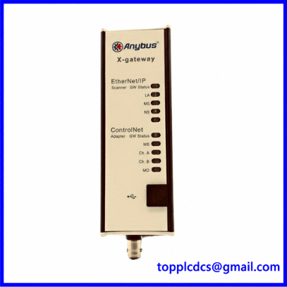
AB7673-F
Technical Specifications
- Brand: HMS Networks
- Product Brand: Anybus
- Model: AB7673-F
- Series: Anybus X-gateway
- Product Name: EtherNet/IP Scanner to ControlNet Adapter
- Product Type: Industrial protocol gateway / network converter
- EtherNet/IP Role: Scanner / Master
- ControlNet Role: Adapter
- EtherNet/IP Adapter Capacity: Up to 64 devices
- EtherNet/IP Data Rate: 10/100 Mbps
- EtherNet/IP Input Data Size: 509 bytes
- EtherNet/IP Output Data Size: 505 bytes
- ControlNet Interface: ControlNet Adapter; network connection uses two BNC connectors according to the interface specification
- Ethernet Connectors: 2 × RJ45
- Configuration Port: USB-B
- Configuration Switches: 8 DIP switches for IP settings
- Configuration Software: Anybus Configuration Manager
- Power Supply: 24 V DC, -20% to +20%
- Typical Current Consumption: 200 mA at 24 V DC
- Maximum Current Consumption: 400 mA at 24 V DC
- Power Connector: 2-pin, 5.08 mm pluggable Phoenix connector
- Reverse Polarity Protection: Yes
- Short-Circuit Protection: Yes
- Electrical Isolation: Yes
- Mounting: DIN-rail, EN 50022
- Dimensions: 114 × 44 × 127 mm (depth × width × height)
- Weight: Approximately 420 g
- Housing Material: Aluminum and plastic
- Protection Rating: IP20
- Operating Temperature: -25°C to +65°C
- Storage Temperature: -40°C to +85°C
- Country of Origin: Sweden
- Place of Manufacture: Sweden, according to manufacturer product information
- Product Status: Confirm the condition of the individual unit from the seller’s listing
- Discontinued: Not confirmed; check HMS Networks for current lifecycle status and support availability
Operating Procedures
1. Preparation
- Check the product label and confirm the model is AB7673-F.
- Confirm that the existing PLC supports ControlNet and the connected devices support EtherNet/IP.
- Prepare the network topology, IP address plan, ControlNet node configuration, and I/O mapping.
- Check the availability of the correct ControlNet BNC cables and Ethernet patch cables.
- Obtain the applicable Anybus Configuration Manager software and gateway documentation.
- Inspect the gateway housing, connectors, DIP switches, and power terminal.
2. Installation
- Mount the gateway on a suitable DIN rail inside the control cabinet.
- Install it in a location with adequate ventilation and accessible wiring.
- Keep the gateway away from excessive heat, moisture, and conductive contamination.
- Maintain appropriate separation between network cables and high-voltage power wiring.
- Confirm that the enclosure and cabinet grounding arrangements meet the installation requirements.
3. Electrical and Network Connection
- Connect a regulated 24 V DC supply to the designated power connector.
- Verify polarity and supply voltage before energizing the gateway.
- Connect the EtherNet/IP network using the RJ45 ports.
- Connect the ControlNet network using the designated BNC connectors.
- Confirm the correct ControlNet cable type and network termination arrangement.
- Connect the USB-B configuration cable when required.
- Check cable shielding, grounding, and connector security.
4. Power-On
- Verify all power and network connections.
- Energize the 24 V DC supply.
- Check the gateway’s status indicators.
- Confirm that the device completes its startup sequence.
- Check the EtherNet/IP and ControlNet network status.
- Investigate communication or configuration faults before enabling data exchange with the machine.
5. Normal Operation
- Monitor the EtherNet/IP and ControlNet communication indicators.
- Confirm that the PLC recognizes the gateway and its configured I/O data.
- Monitor input and output data exchange.
- Check for network interruptions, adapter connection faults, and data mapping errors.
- Record communication status and diagnostic messages during normal operation.
6. Configuration
- Connect a PC to the USB-B configuration port.
- Open the supported Anybus Configuration Manager software.
- Configure the EtherNet/IP IP address and related network settings.
- Set the EtherNet/IP scanner parameters and adapter connections.
- Configure the ControlNet adapter settings according to the PLC network design.
- Define the required input and output data sizes and mappings.
- Verify the ControlNet node address and network configuration.
- Download the configuration and restart the gateway if required.
- Confirm that the PLC and connected EtherNet/IP devices exchange the expected data.
7. Shutdown
- Place the controlled machine in a safe state before interrupting network communication.
- Stop or disable dependent control sequences according to the machine procedure.
- Isolate the 24 V DC supply.
- Disconnect network and configuration cables only when required.
- Record the existing configuration before removing or replacing the gateway.
Daily Maintenance
- Check the power and network status indicators.
- Inspect Ethernet and ControlNet cables for damage or loose connections.
- Confirm that the gateway remains securely mounted on the DIN rail.
- Check the cabinet temperature and ventilation.
- Inspect the power connector and network connectors for signs of corrosion or overheating.
- Monitor PLC communication diagnostics for intermittent faults.
- Keep a backup of the gateway configuration.
- Verify that network addressing and I/O mapping remain consistent with the PLC project.
- Keep the enclosure clean and free from dust and conductive contaminants.
- Record communication interruptions and maintenance activities.
Troubleshooting
1. Gateway does not power on
- Check the 24 V DC power supply.
- Verify polarity at the 2-pin power connector.
- Inspect the supply wiring and protective devices.
- Confirm that the supply can provide the required current.
2. EtherNet/IP communication failure
- Check the Ethernet cable and RJ45 connections.
- Verify the gateway IP address and subnet settings.
- Confirm that the PLC or scanner configuration matches the gateway settings.
- Check for duplicate IP addresses or incorrect adapter configuration.
3. ControlNet communication failure
- Inspect the BNC connectors and ControlNet cable.
- Verify the node address and network configuration.
- Check network termination and cable condition.
- Review the PLC’s ControlNet diagnostic information.
4. PLC does not recognize the gateway
- Confirm that the correct gateway model and network role are configured.
- Check the ControlNet adapter configuration.
- Verify the applicable EDS file and PLC project settings.
- Confirm that the network is operating at the required communication parameters.
5. I/O data is incorrect
- Review the configured input and output data sizes.
- Check the data mapping and byte offsets.
- Confirm that the PLC tags correspond to the gateway’s configured I/O layout.
- Verify the source device’s data format and update behavior.
6. Intermittent communication
- Inspect network cables and connectors.
- Check grounding, shielding, and cabinet electrical noise.
- Review network status indicators and PLC fault logs.
- Check whether excessive network loading or incorrect topology is affecting communication.
Safety Precautions
- Installation and commissioning must be performed by qualified industrial automation personnel.
- Disconnect the 24 V DC supply before changing wiring or removing the gateway.
- Verify power polarity and voltage before energizing the unit.
- Do not connect the ControlNet interface to an Ethernet port or assume that visually similar connectors are interchangeable.
- Use the correct ControlNet coaxial cable, connectors, and termination components.
- Follow the specified network topology and node-addressing rules.
- Do not change IP addresses or I/O mappings on an operating production system without an approved change procedure.
- Back up PLC and gateway configurations before making network changes.
- Observe the IP20 protection rating; install the unit inside a suitable control cabinet.
- Do not exceed the specified operating temperature or electrical ratings.
Product Keywords
HMS Networks AB7673-F, Anybus X-gateway, Anybus protocol converter, EtherNet/IP to ControlNet gateway, EtherNet/IP Scanner, ControlNet Adapter, industrial communication gateway, PLC network converter, industrial Ethernet gateway, ControlNet integration, 24 V DC gateway, machine automation communication, HMS Anybus spare parts.
For industrial automation products and spare parts, visit https://www.newplcdcs.com.
Related HMS Networks / Anybus Models and Product Families
The following products belong to related Anybus gateway and industrial communication product families. They are not confirmed direct replacements for AB7673-F.
- AB7635-F – Anybus X-gateway DeviceNet Adapter to Modbus TCP Server
- AB7899-F – Anybus X-gateway Modbus RTU to Modbus RTU
- AB7539-F – Anybus X-gateway Modbus Plus to POWERLINK
- AB7566-F – Anybus X-gateway Interbus Copper Slave to OPC UA/MQTT
- AB7000 Series – Anybus X-gateway family
- AB7300 Series – Anybus X-gateway family
- AB7500 Series – Anybus X-gateway family
- AB7600 Series – Anybus X-gateway family
- AB7800 Series – Anybus X-gateway family
- AB9000 Series – Anybus X-gateway family
- Anybus Communicator – Serial-to-industrial Ethernet gateway family
- Anybus CompactCom – Embedded communication interface family
- Anybus Wireless Bolt – Industrial wireless communication product family
- Anybus Wireless Bridge – Industrial wireless bridge family
- Anybus Diagnostics – Industrial network diagnostics product family