Description
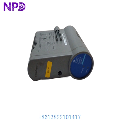
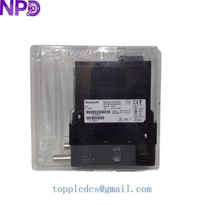
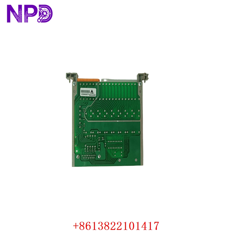
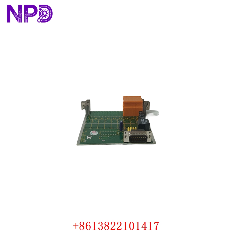
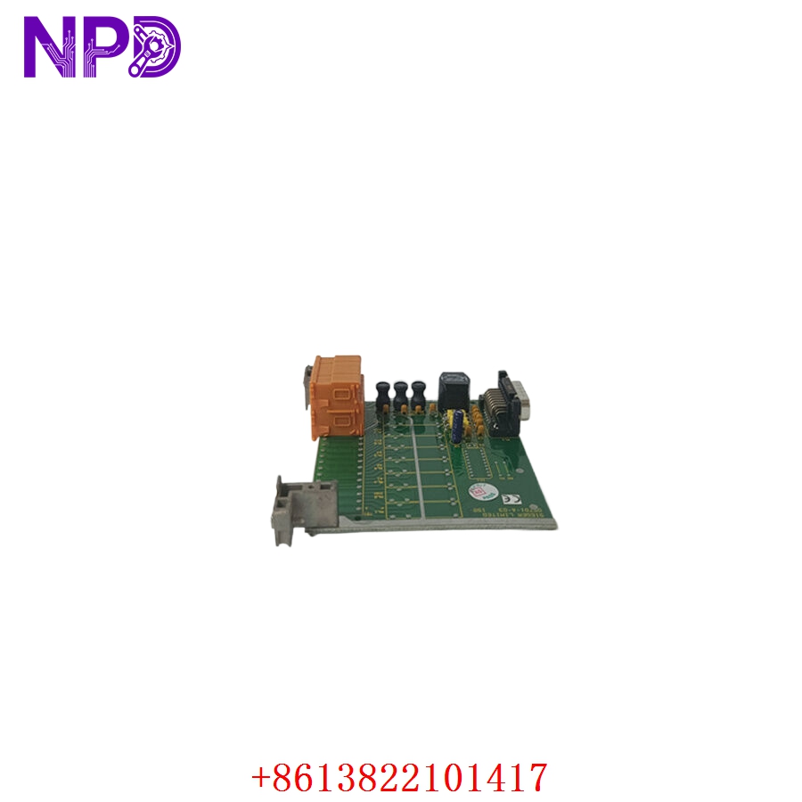
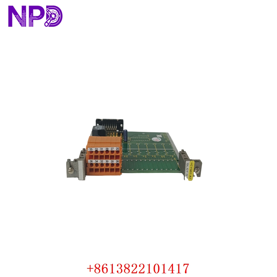
- Model: HONEYWELL 05701-A-0326
- Brand: Honeywell Analytics / Zellweger Sieger
- Series: System 57 (5701 Control Platform)
- Core Function: Connects field-mounted gas detectors directly to the single-channel control card, routing sensor signals into the monitoring rack.
- Condition: Brand New Surplus (Original factory packaging, non-refurbished)
- Product Type: Field Interface Card (FIC) – Sensor Input Only (No Onboard Relays)
- Key Specs: 9 V DC to 32 V DC Input | Passive Signal Pass-Through & Amplification | Supports 4-20 mA or Catalytic Bridge Sensors
- Operating Input Voltage: 9 V DC to 32 V DC (Derived from subrack backplane)
- Onboard Switching Relays: None (Optimized purely for signal interface; avoids parasitic relay power draw)
- Supported Input Types: 3-wire 4-20 mA source, 4-wire isolated current loop, or 3-wire Catalytic Bridge sensors
- Output Signal to Control Card: 0 V DC to 5 V DC scaled signal
- Wiring Terminal Compatibility: Accepts solid or stranded conductors up to 2.5 mm² (14 AWG)
- Isolation Enclosure Rating: IP20 (Rear-chassis card format)
- Card Dimensions: 16.0 cm x 10.9 cm x 4.3 cm
- Weight: 0.09 kg (0.20 lbs)
- Chassis Capacity: Occupies one rear interface slot directly behind the 5701 Control Card
- Standards Compliance: CE marked, EMC Directive compliant
HONEYWELL 05701-A-0326
HONEYWELL 05701-A-0326
HONEYWELL 05701-A-0326
HONEYWELL 05701-A-0326
Application Scenarios & Engineering Pain Points
In life-safety gas monitoring networks, the field interface card is the unsung hero. It sits at the back of the rack, acting as the physical landing point for long, shielded field runs coming from toxic and combustible gas sensors out in the plant.
The biggest engineering headache with the Honeywell System 57 platform happens when field modifications or moisture ingress down the line short out a sensor wire. If a high-voltage surge punches through the field wiring, the 05701-A-0326 acts as the sacrificial buffer layer. It takes the hit to protect the high-dollar processing control cards sitting in the front of the rack. When this interface card degrades or suffers component fatigue, the corresponding channel drops offline, throwing a system “Fault” alarm that compromises your facility’s safety interlocks.
Typical Field Deployments:
- Refineries and Petrochemical Plants – LEL Combustible Gas Monitoring
Lands inputs from catalytic bead or infrared sensors monitoring lower explosive limits (LEL) around pump rows and storage tank dikes.
- Semiconductor Cleanrooms – Toxic Gas Detection Arrays
Interfaces with highly sensitive 4-20 mA gas transmitters (like the Honeywell Midas) to track trace leaks of phosphine, arsine, or silane.
- Wastewater Treatment Facilities – H2S and Oxygen Deficiency Monitoring
Monitors wet wells and chemical dosing rooms for hydrogen sulfide gas buildup and dangerous drops in oxygen levels.
Case Study: The Shorted Sensor Loop in a Wet Well
- The Setup: A municipal wastewater facility relied on a half-rack Honeywell System 57 monitor to track ambient H_2S levels inside a primary extraction gallery. The field lines terminated into a series of 05701-A-0326 cards at the rear of the panel.
- The Crisis: Heavy condensation inside an overhead conduit leaked into a junction box, causing a direct short circuit on Channel 4’s sensor power loop. The localized power spike instantly cooked the input conditioning circuit on the interface card. Channel 4 threw a latching system fault. This fault crippled the automated ventilation override circuit, forcing the plant manager to suspend physical entry permits for maintenance crews.
- The Fix: The instrument tech recognized that while the front control card was undamaged, the rear field interface card was completely non-responsive. The local distributor flagged the module as a factory lead-time item. The manager reached out to our depot. We checked our inventory, verified a brand-new 05701-A-0326 card on our bench, and shipped it via overnight express.
- The Outcome: Arriving by 9:00 AM the following morning, the tech isolated the rack power, unscrewed the terminal strip without touching the front-facing logic cards, and swapped the card out. The short-circuit fault cleared immediately on reboot, the sensor loop recalibrated perfectly, and physical work permits were safely reauthorized before noon.
Standard Operating Procedure (SOP) Quality Transparency
Because life-safety systems leave no room for guesswork, our QA workshop processes every single 05701-A-0326 through a rigorous five-step functional verification routine before packaging:
[Visual Trace & Pin Audit] ➔ [Backplane Interface Fitting] ➔ [Loop Simulation Test] ➔ [Insulation Integrity Check] ➔ [ESD Unit Sealing] 1. Visual Trace and Pin Audit
- Geometric Inspection: We examine the card artwork, terminal screw threads, and edge pins under high magnification to confirm that the component is completely pristine, free of factory solder bridges, micro-fractures, or oxidation.
- Revision Check: Part numbers and manufacturing tracking marks are audited to verify absolute physical consistency with genuine Honeywell Analytics specifications.
2. Backplane Interface Fitting (Live System Test)
- Test Architecture: The interface card is fitted into an authentic Honeywell System 57 subrack frame linked directly behind a standard 5701 single-channel control module.
- Power-Up Dynamics: We power the rack via a stabilized DC source, tracking the power draw to confirm it stays within the nominal ~5 W threshold with zero startup fluctuations.
3. Signal Simulation and Loop Testing
- 4-20 mA Input Validation: Using a calibrated signal generator, we inject precise 4.0 mA, 12.0 mA, and 20.0 mA currents into the terminal landings. We check that the corresponding front-end card receives the mapped 0-5 V DC internal scaled voltage with zero signal attenuation.
- Open/Short Fault Emulation: We deliberately simulate open-circuit and short-circuit conditions on the test loop to ensure the card passes fault signals cleanly to the controller rack without locking up.
4. Insulation Integrity Check
- Dielectric Testing: We verify the dielectric isolation paths between the terminal blocks and the grounding logic plane to ensure excellent noise immunity and field surge protection.
5. ESD Unit Sealing and Logistics Tracking
- Static Defense: The verified card is packed directly into an ESD anti-static pouch within a certified static-safe station.
- Physical Armor: The sealed pouch is cocooned in dense shock-resistant foam inside a rigid industrial box to prevent physical component stress during international flight transits.
- Certification: Every box is tagged with a physical QC Passed certificate.
Technical Pitfall Mitigation Guide
While the 05701-A-0326 is a modular part, forgetting how it interacts with the rest of the System 57 rack can cause commissioning headaches.
1. The Relay Discrepancy Trap
- The Risk: The 05701-A-0326 is a No-Relay / Sensor Input Only card. If your legacy panel was designed to trigger local exhaust fans or strobe lights directly from relays located on the rear interface card (such as the 05701-A-0327 or 05701-A-0328 variants), dropping the -0326 into that slot will leave those physical field alarms completely dead.
- The Fix: Verify your panel drawing before buying. If your system triggers external safety devices through the master engineering card or a separate dedicated relay module, this -0326 card is exactly what you want. If you need local changeover contacts directly on the channel card, verify the exact part suffix required.
2. Terminal Coding Plug Realignment
- The Risk: System 57 subracks use physical keying keys or specific terminal block positions. Forcing a card onto a misaligned or differently wired terminal socket can bend the backplane header pins.
- The Fix: Hand-align the card carefully along the guide rails of the rear chassis. It should slide in smooth and seat securely with minimal pressure. If you feel resistance, stop immediately. Check for terminal block misalignment or bent pins.
3. Shield Grounding and Earth Loops
- The Risk: Mismanaging the drain wire on your shielded sensor cable can introduce ground loops, making your gas readings jump erratically on the HMI screen.
- ❗ Important Note: Always land the sensor cable shield at the designated ground terminal on the interface card rack frame, and ensure the outer field end of the shield is clipped clean and taped isolated. Never ground both ends of the shield wire.
Compatible Replacement Models
If you are mapping out long-term maintenance cycles or modifying your gas rack layout, note these relative alternative profiles:
| Original Model | Potential Alternative | Compatibility Level | Key Differences | Necessary Field Action | Cost Impact |
| 05701-A-0326 | 05701-A-0327 | ⚠️ Software Compatible | Includes onboard A1, A2, and Fault Single Pole Changeover (SPCO) relays. | You can use it as an alternative, but you must check terminal schematics because the terminal footprint expands to accommodate the physical relay contacts. | Higher cost layout due to physical relay components (+40%). |
| 05701-A-0326 | 05701-A-0328 | ⚠️ Software Compatible | Triple relay card configuration variant (adds A3 and Inhibit relays). | Requires adjusting the physical space layout at the back of the subrack to land the additional relay loops. | Significant premium cost variation (+60%). |
| 05701-A-0326 | Honeywell Touchpoint Platform | ❌ Total Retrofit Required | Complete modern system migration pathway using decentralized digital communication links. | Requires replacing the entire System 57 rack, updating all field gas transmitter units, and running new wiring topology throughout the facility. | High capital and project engineering layout (>400%). |
Troubleshooting Quick Reference
Use this direct matrix to isolate issues at the back of the panel when troubleshooting a problematic channel:
| Diagnostic Symptom | Root Cause Probability | Card Relevance | Field Verification Steps | Recommended Remediation |
| Front card reads “Fault”, sensor loop current reads 0.0 mA | Open field circuit, loose terminal screw, or blown input trace on the card. | ⚠️ Medium | Disconnect field lines and attach a loop calibrator directly to the input terminals on the 05701-A-0326. Inject a solid 12.0 mA signal. | If the front display now reads normally, your interface card is perfectly fine; search for a broken wire out in the field. If the rack still shows a fault with a local source attached, the card’s input stage is dead. Swap it. |
| Gas readings fluctuate wildly on a single channel | Induced electromagnetic noise or loose terminal clamp. | ⚠️ Medium | Check the terminal screws on the rear card. Ensure they are torqued down snugly to 0.5 Nm. Verify that the shield drain wire is landed properly to earth ground. | If the terminal is tight and the shielding is correct but the drift persists when swapping with an adjacent channel card, replace this interface card. |
| System operates properly but no alarms trip local horn/strobe | Wrong hardware selection used during a repair cycle. | ✅ High | Look at the model stamp on the face of the card. Confirm if the card is an 05701-A-0326. | This module features no onboard relays. If your local circuit requires physical dry contacts at the rear terminal block, you must replace this card with an 05701-A-0327 or -0328 card. |
Need immediate engineering backup? If your plant is down and you cannot pinpoint the failure node, drop our technical support desk an email with photos of your current indicator lights and a copy of your panel’s wiring diagram. We will have an integration engineer respond within 2 hours.