
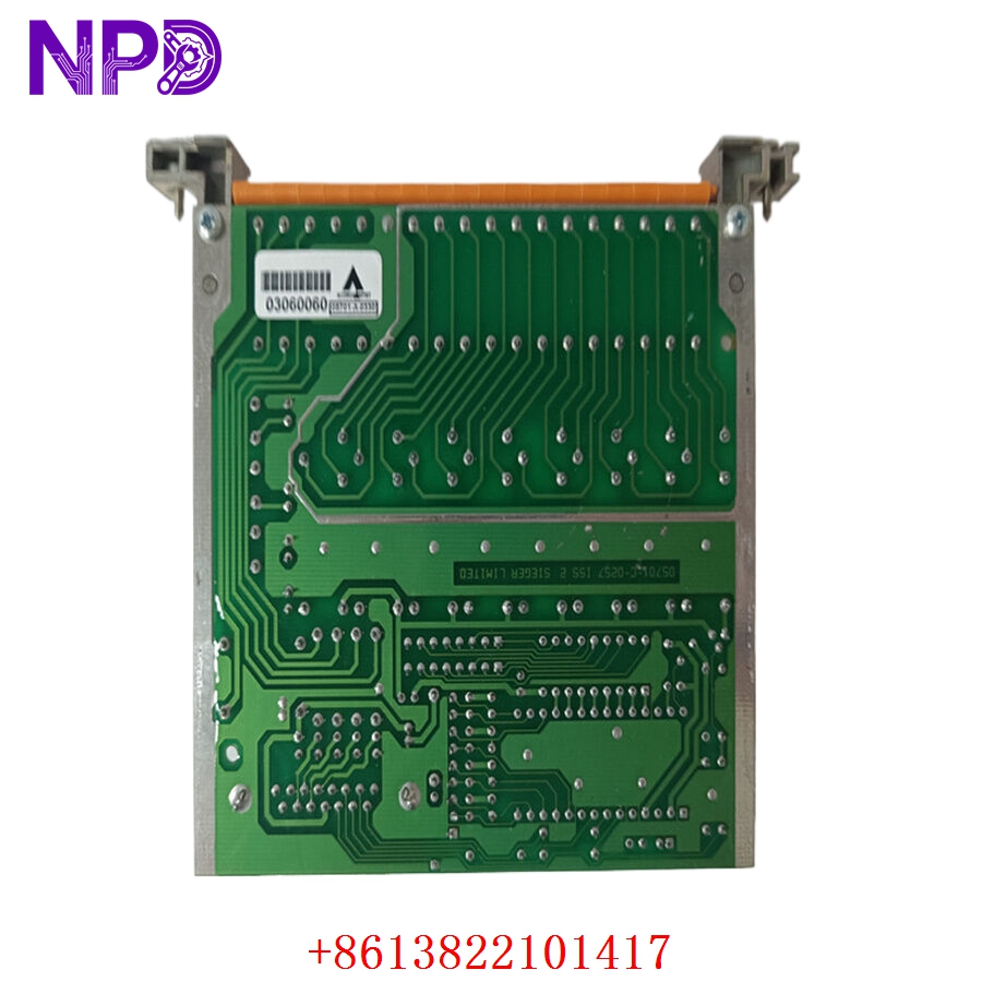
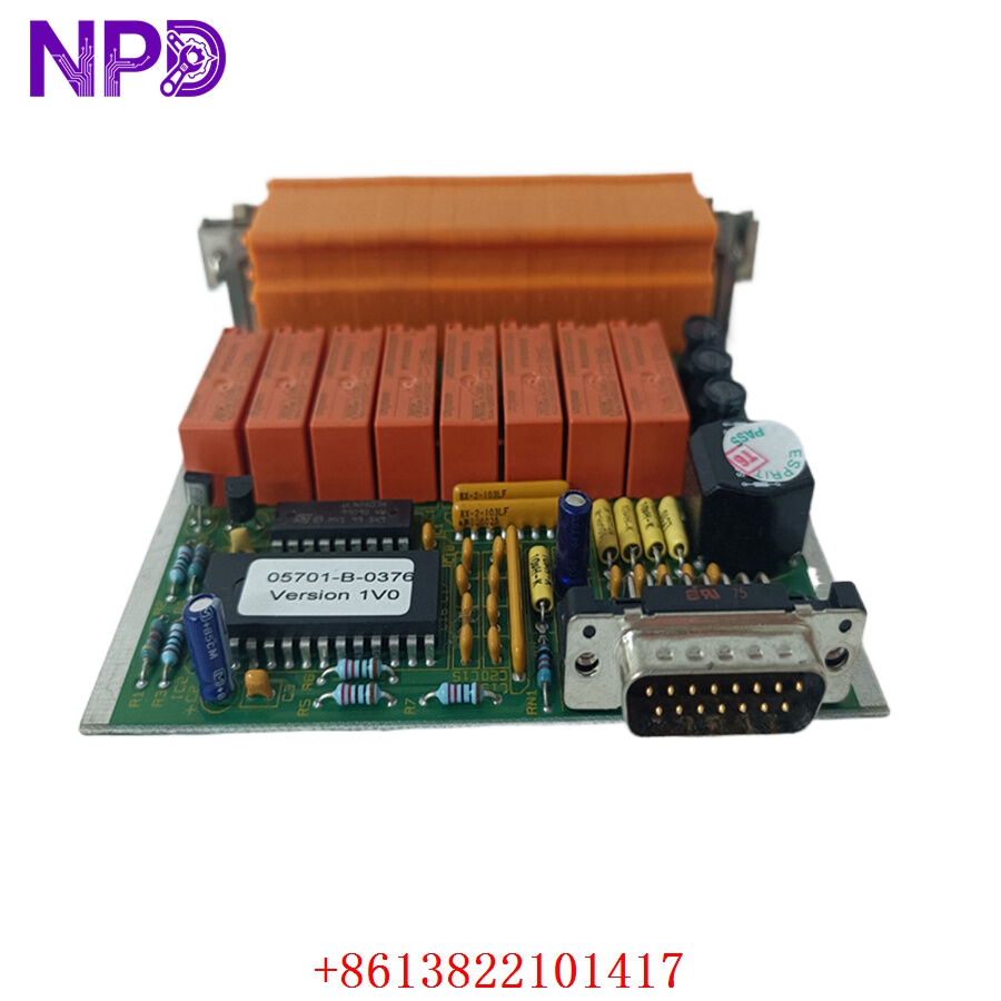
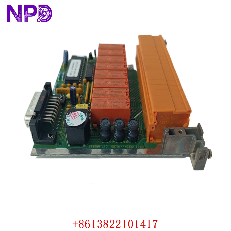
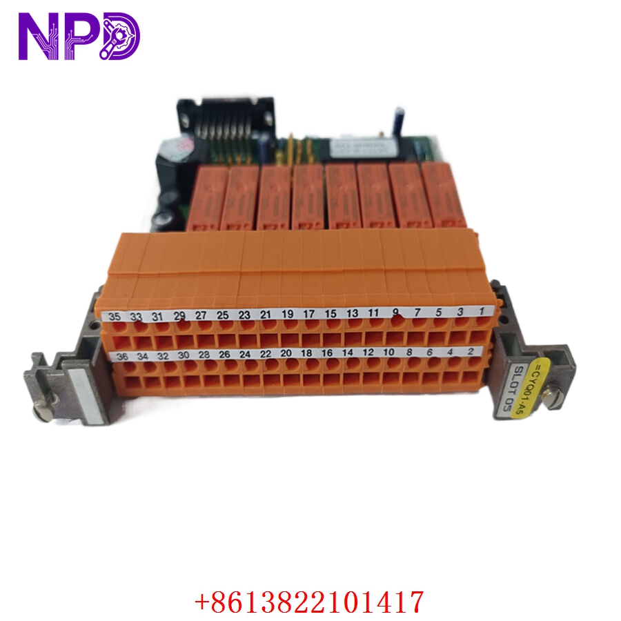
Description
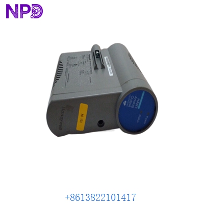
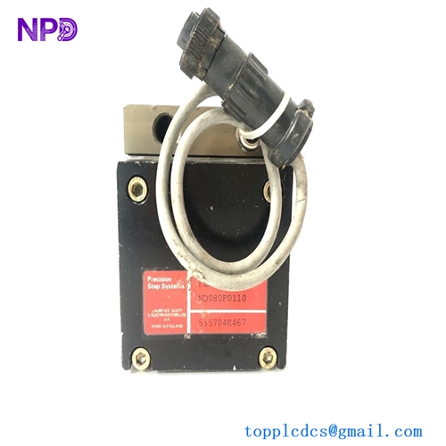
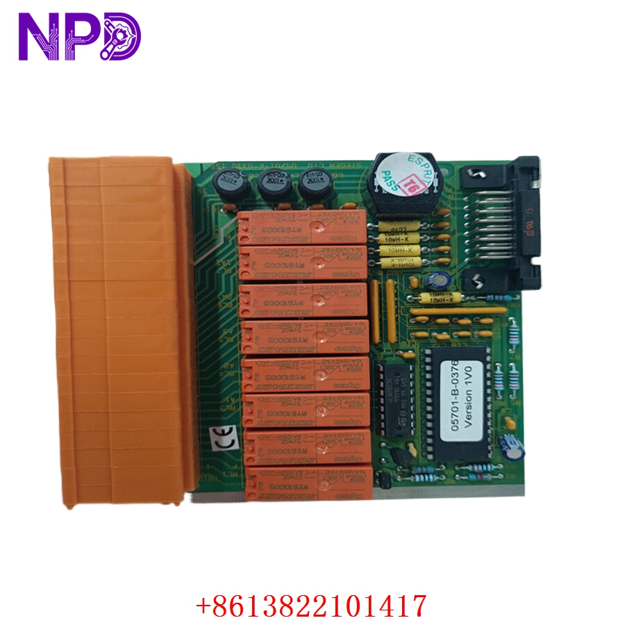
- Model: HONEYWELL 05701-A-0330
- Brand: Honeywell (USA) / Analytics division
- Series: System 57 Gas Detection Series
- Core Function: Four-channel discrete monitoring and control card for gas detection transmitter networks
- Condition: Brand New Surplus (Original authentic stock, never energized, zero field use or rework)
- Product Type: 4-Channel Gas Control Card / Monitoring Module
- Key Specs: 4 independent sensor inputs, multi-line back-lit LCD screen, triple alarm relays per channel
- Operating Input Voltage: 21 V DC to 32 V DC nominal supply via the System 57 backplane rail
- Power Dissipation: 3.5 W nominal load (excluding connected sensor drive current)
- Input Signal Range: 4 to 20 mA analog current loop per channel, or catalytic bead bridge inputs
- Sensor Excitation: Provides up to 200 mA constant current loop to remote gas sensor heads
- Relay Outputs: 3 programmable alarm level relays and 1 dedicated fault relay per channel
- Contact Rating: 5 A at 250 V AC / 30 V DC non-inductive load thresholds
- Display Interface: Integrated front-panel alphanumeric LCD with bar-graph readout profiles
- Operating Temperature: -10°C to +55°C ambient air envelope
- Storage Temperature Envelope: -25°C to +75°C maximum limits
- Humidity Tolerance: 0% to 95% relative humidity (RH, non-condensing)
- Configuration Port: Front-panel engineering serial interface for software utility mapping
- Mechanical Footprint: Single-slot Eurocard configuration pluggable into standard 3U System 57 racks
HONEYWELL 05701-A-0330
HONEYWELL 05701-A-0330
HONEYWELL 05701-A-0330
HONEYWELL 05701-A-0330
Installation & Configuration Guide
Pre-Installation Setup
⚠️ CRITICAL SAFETY WARNING:
- Coordinate a formal bypass window with the plant safety desk before pulling or modifying any gas detection cards.
- Ensure all automated area fire suppression or emergency venting interlocks linked to this card are placed in manual override mode.
- Verify that the remaining cards in the active System 57 rack are operating cleanly before working on the target slot.
- Use an insulated probe to check for high external voltages if the relay output loops track to external 250 V AC siren circuits.
- Required Tools & Gear:
- Grounded anti-static wrist strap connecting directly to the cabinet steel earth lug.
- Standard 2.5 mm precision flathead screwdriver for card retention screws.
- Digital multimeter (such as a Fluke 87V) with fine-tipped test leads.
- Specialized Honeywell System 57 configuration software tool or engineering terminal device.
- Handheld camera or phone for documenting rear terminal block card tracking layouts.
- Backup Procedures:
- If the card is still responding intermittently, extract its current alarm parameters, calibration curves, and gas target levels via the front engineering port.
- Note the exact card slot configuration number within the primary sub-rack frame.
- Document the precise physical position of all hardware configuration jumpers located along the side of the card PCB layout.
Old Card Removal
- Engage Bypasses: Press the front panel button sequence to place the target card into “Inhibit” mode. This forces a steady signal output to prevent triggering false safety alarms while unseating connections.
- Loosen Securing Fasteners: Back out the top and bottom captive screws located on the card front bezel using your flathead screwdriver.
- Eject the Module: Pull the card’s integrated extraction handles outward at the same time to break the friction bond with the heavy backplane edge pins.
- Slide out safely: Draw the card straight forward along its plastic track guides. Hold the assembly by its front panel plate or PCB margins and place it flat on your ESD mat.
New Card Mounting and Configuration
- ESD Mitigation: Keep your grounded wrist strap attached while removing the new module from its silver anti-static shielding package. Do not touch the gold contact traces on the edge connector.
- Hardware Configuration Setup: Look at your reference photos of the old card. Replicate the exact positions of any physical jumper blocks on the new board’s PCB surface. These jumpers set the input parameters for either a 4–20 mA current loop input or a direct catalytic bead pellistor bridge sensor loop.
- Chassis Alignment: Align the top and bottom edges of the new card with the empty slot track guides in the System 57 sub-rack. Slide the module smoothly backward until the rear interface connector makes initial contact with the backplane pin array.
- Secure Fasteners: Press the card firmly home until the front plate sits flush against the frame margins. Tighten the top and bottom captive securing screws down snug (do not overtighten, roughly 0.5 N·m torque) to maintain a solid frame ground connection.
Post-Installation Verification Checklist
- [ ] Confirm all onboard configuration jumpers match the original card’s sensor input settings perfectly.
- [ ] Verify that front panel retaining screws are completely threaded down snug.
- [ ] Check that neighboring monitoring cards in the sub-rack have not been jarred out of place.
- [ ] Ensure that the card is fully seated and the alphanumeric display powers up instantly on initialization.
Power-Up & Loop Commissioning
- Once the card is seated, the System 57 rack backplane supply will automatically energize the card’s internal logic lines.
- Observe the front-facing LED diagnostics assembly array and display:
- Power (Green): Solid green indicates the internal DC-to-DC converters are delivering correct local operating rails.
- Fault (Yellow): Flashing yellow means the card is in a startup state or recognizes an open/shorted external sensor loop circuit.
- Inhibit (Yellow): Steady amber means the card remains safely isolated from executing external trip actions.
- Plug your engineering terminal interface tool into the front configuration port. Verify that the firmware revision level aligns with your site standard database requirements.
- Download your archived gas target profiles, gas calibration curves, and custom alarm setpoints (A1, A2, A3 values) straight to the card’s non-volatile flash memory.
- Take the card out of inhibit mode once the field sensor readings settle out and stabilize on the LCD bar-graph view.
- Run a functional loop test: inject a verified sample of calibration gas (e.g., 50% LEL methane test mix) directly onto the remote sensor head. Verify that the card’s front LCD tracks the gas concentration spike accurately, lights the alarm LEDs at the designated trip targets, and changes the state of the onboard output relays smoothly.
- Once the loop clears and returns to ambient background levels, log the serial number into your plant maintenance tracking database and sign off the card as fully active.
Customer Cases & Industry Applications
Case 1: Offshore Production Platform Gas Detection Restoration
An oil and gas extraction platform operating in the North Sea experienced an unexpected failure on a gas monitoring card in its primary safety cabinet. The fault put four critical hydrocarbon gas monitoring heads in the processing room into an offline state, reducing safety visibility and violating maritime safety regulations.
The procurement group was quoted a 12-week factory delivery window for a replacement module. To avoid a forced production shutdown, they reached out to us to check our ready surplus stock for an 05701-A-0330 module. We retrieved a brand-new surplus card from our warehouse, mounted it onto our System 57 functional verification frame, and ran a continuous 24-hour communications and relay load test. The part was packed securely and sent via express priority air courier, reaching the platform’s shore base within 48 hours. Shipboard technicians completed the slide-in installation, loaded the target parameters, and restored full safety system operations without any issues.
Case 2: Steel Mill Blast Furnace Safety System Maintenance
A large steel production plant utilized a Honeywell System 57 rack setup to monitor carbon monoxide (CO) concentrations around its main blast furnace work decks. During a scheduled safety audit, a technician found that an existing monitor card had sustained severe internal heat stress over years of operation, causing sporadic measurement drift on two of its four input lines.
[Blast Furnace CO Monitor Drift] ──> [Critical Safety Risk Flagged]
                                                │
                ┌───────────────────────────────┴───────────────────────────────┐
                ▼                                                               ▼
  [Option A: Full System Migration]                                [Option B: Direct Surplus Card Swap]
  • Cost: High capital expenditure (~$85,000)                      • Cost: ~75% savings vs full upgrade path
  • Downtime: 4 days of rewiring and downtime                      • Downtime: Completed in under 15 minutes
  • Execution Risk: High loop recoding workload                    • Execution Risk: Zero wiring adjustments needed
The plant management team wanted to avoid an expensive system upgrade since the furnace line was scheduled for a complete capital overhaul in three years. They chose to replace the individual card by ordering a new surplus unit from us. We supplied a brand-new 05701-A-0330 module featuring factory conformal coating protection to resist dust and moisture. The plant crew installed the replacement card, transferred the existing channel configurations, and recalibrated the loops in less than fifteen minutes. This quick drop-in swap eliminated the measurement drift, maintained safety standards, and avoided an unplanned capital upgrade project.
Frequently Asked Questions (FAQ)
Q1: Does the 05701-A-0330 card work with both catalytic bead and 4–20 mA gas sensors?
A: Yes, it does. The card is designed with internal hardware jumper blocks on the main circuit board that allow you to select your input type. You can set up each channel independently to handle either a 3-wire catalytic bead bridge sensor (like a Honeywell 705 transmitter) or a standard 2-wire/3-wire 4 to 20 mA analog input transmitter loop (like a Searchpoint Optima Plus). Make sure to set these physical jumpers to match your specific field equipment layout before sliding the card into the live backplane.
Q2: What causes a persistent “Fault” LED on the front panel immediately after installing the module?
A: A yellow fault light usually means the card is detecting an issue with the external wiring path or the attached sensor. Common causes include:
- An open-circuit or short-circuit condition on the field wiring lines.
- Missing external loop excitation power on the rear terminal blocks.
- A mismatch between the onboard physical jumper settings and the actual sensor type connected to that channel.
- The channel parameters in the configuration software are enabled, but no physical sensor is attached to those terminal blocks.
Q3: How do you verify the functionality of the onboard alarm relays before shipping?
A: Our testing process goes far beyond a simple visual check. We place every module into an authentic Honeywell System 57 sub-rack and connect it to an automated loop simulator.
[System 57 Test Sub-Rack] ──> [05701-A-0330 Card] <──> [Loop Simulator & Load Bank]
                                                               │
                                                               ▼
                                              [Multi-Point Relay Operation Test]
We inject custom input signals to drive each channel past its A1, A2, and A3 alarm thresholds, and connect a load bank to the relay contacts to confirm they open and close cleanly under real-world current loads. This rigorous testing ensure that the module’s safety interlocks will perform reliably when deployed in your plant.
Q4: Is this card fully compatible with older System 57 control racks?
A: Yes, the 05701-A-0330 card is designed to be fully backward compatible with standard System 57 3U rack frames. It uses the standard Eurocard form factor and connects cleanly to standard backplane pin layouts. To ensure everything runs smoothly, check that your sub-rack power supply has enough spare capacity to drive the new module, especially if you are adding cards to an empty slot rather than replacing an existing unit.
Q5: Can our site instrumentation engineers modify the alarm levels using the buttons on the front panel?
A: The front panel buttons allow you to reset latched alarms, view specific channel details, and place the card into inhibit mode. However, to make structural modifications to the alarm setpoints, gas target tags, or relay operating logic, you must connect an engineering terminal or a laptop running the Honeywell configuration software to the front serial port. This requirement protects the unit from unauthorized or accidental changes to critical safety parameters.
Q6: What payment methods do you accept for urgent shipments during a plant emergency?
A: We accept international wire transfers (T/T), corporate credit cards, and standard letters of credit. For urgent situations involving a safety system outage, send over a copy of your bank’s wire transfer confirmation slip. Our logistics team can then expedite your order, complete the testing protocols, and hand off the module to an express courier before the funds clear our account.