Description
Product Description
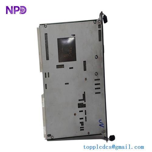
The Honeywell 05701-A-0361 Issue 4 Engineering Card is a dedicated engineering interface module designed for the Honeywell System 57 gas detection control system. It provides centralized access to commissioning, configuration, operation, and diagnostic functions for the control cards installed in a System 57 rack. The module handles backplane serial communication, system clock functions, and routing of the 24 V DC supply from the DC Input Card to the rack backplane. Its front panel features status LEDs, tactile push-buttons, and a Mini-DIN engineering interface for connection to compatible computers, serial printers, or engineering keys. Supported functions include alarm setpoint adjustment, sensor zero and span calibration, catalytic sensor current monitoring, sensor line monitoring, alarm inhibit control, and system clock adjustment. The 05701-A-0361 is installed in the right-hand slot of the System 57 rack and is intended for use with compatible Honeywell 5701 and 5704 control system configurations.
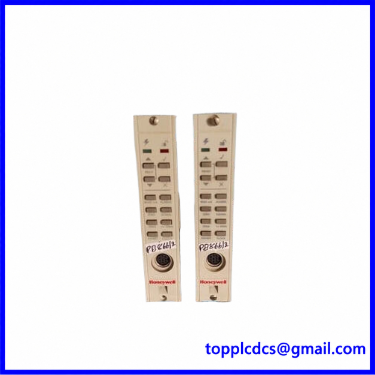
80026-044-06
Product Datasheet – 10 Parameters
- Brand: Honeywell Analytics / Sieger
- Model: 05701-A-0361
- Series: System 57 / 5701 Control System
- Product Name: Engineering Card
- Manufacturer: Honeywell Analytics
- Product Status: Discontinued by Manufacturer
- Dimensions: 132 × 25 × 170 mm
- Weight: Approximately 152 g
- Country of Origin: Not independently verified; check nameplate
- Power Requirements: 18–32 V DC, nominal 24 V DC; typical power consumption 1.5 W
Additional Technical Specifications:
- Mounting Position: Right-hand slot of System 57 rack
- Backplane Interface: Serial communication controller and monitor
- External Interface: RS-232
- Front Connector: Mini-DIN engineering interface
- Indicators: Power On and Unlocked LEDs
- Controls: Up, Down, Accept, Reject, and Print
- Sensor Functions: Zero, span, first span, and catalytic bead current adjustment
- Alarm Functions: Alarm setpoint checking, adjustment, testing, and inhibit control
- Clock Function: System date and time adjustment
- Diagnostic Function: Internal circuit and backplane communication self-validation
⚙️ Operating Instructions and Usage
1. Installation and Preparation
- Confirm the part number 05701-A-0361 and Issue 4 revision.
- Verify compatibility with the installed System 57 rack.
- Switch off and isolate the rack power supply before installation.
- Install the Engineering Card in the designated right-hand rack slot.
- Check the backplane connector and module alignment.
- Verify that the DC Input Card supplies the correct 24 V DC nominal voltage.
- Inspect the Mini-DIN engineering connector.
- Check the rack communication bus and connected control cards.
- Confirm that the engineering key and authorized configuration tools are available when required.
2. Power-On Sequence
- Confirm that all System 57 modules are correctly installed.
- Verify the rack DC power supply and polarity.
- Check the backplane connections.
- Energize the rack according to the approved system procedure.
- Allow the Engineering Card to initialize.
- Check the green Power On LED.
- Check the communication status of the rack.
- Verify that the installed control cards are recognized.
- Check for system faults before performing commissioning operations.
3. Normal Operating Procedure
- Confirm that the System 57 rack is operating normally.
- Check the Engineering Card status indicators.
- Use the front-panel buttons to access the required engineering functions.
- Select the appropriate control card or sensor channel.
- Review the current sensor signal and alarm status.
- Check configured alarm thresholds.
- Monitor catalytic sensor current where applicable.
- Review zero and span calibration values.
- Check the system clock and event information.
- Confirm that all control cards return to normal operating status after engineering operations.
4. Shutdown Procedure
- Confirm that gas detection coverage remains available through an approved alternative arrangement if the rack must be shut down.
- Notify the responsible control room or plant operator.
- Place the affected system in the approved maintenance condition.
- Confirm that any alarm inhibit or maintenance bypass is properly controlled.
- Isolate the rack power supply.
- Verify that the card is de-energized.
- Remove the Engineering Card only after electrical isolation.
- Protect the card and backplane connector against dust and electrostatic discharge.
5. Parameter Setting and Modification
- Use the Engineering Card front-panel keypad to access configuration functions.
- Connect a compatible engineering computer through the Mini-DIN RS-232 interface when required.
- Use the authorized engineering key to unlock protected functions.
- Back up or record existing settings before making changes.
- Select the required control card and sensor channel.
- Review alarm setpoints before adjustment.
- Perform sensor zero calibration according to the detector manufacturer’s procedure.
- Perform span calibration using the approved calibration gas.
- Check catalytic sensor bead current where applicable.
- Configure sensor line monitoring and system clock settings.
- Use alarm inhibit only under an authorized maintenance procedure.
- Confirm and save changes, then verify the complete gas detection system response.
6. Maintenance and Safety Precautions
- Do not remove the Engineering Card while the rack is energized.
- Do not perform calibration without the correct certified test gas and equipment.
- Never leave critical gas detection channels inhibited after maintenance.
- Do not change alarm thresholds without engineering authorization.
- Check the Power On and communication indicators regularly.
- Inspect the Mini-DIN connector and backplane contacts.
- Keep a record of calibration settings and alarm configuration changes.
- Perform a complete functional test before returning the gas detection system to normal service.
🔧 Recommended 15 Other Honeywell System 57 Models
- 05701-A-0301 – Single Channel Control Card
- 05701-A-0325 – DC Input Card
- 05701-A-0361 – Engineering Card
- 05701-A-0405 – 16-Way AC/DC Power Supply Assembly
- 05701-A-0406 – 8-Way AC/DC Power Supply Assembly
- 05701-A-0440 – 50 W Power Supply Module
- 05701-A-0441 – Power Supply Subunit
- 05701-A-0451 – 16-Way System 57 Cabinet
- 05701-A-0452 – 8-Way System 57 Cabinet
- 05701-A-0501 – 16-Way Front-Access Rack
- 05701-A-0502 – 8-Way Front-Access Rack
- 05701-A-0511 – 16-Way Rear-Access Rack
- 05701-A-0512 – 8-Way Rear-Access Rack
- 05701-A-0550 – Engineering Key Kit
- 05701-A-0551 – Engineering Interface Kit
Replacement Note: The 05701-A-0361 is a rack-level engineering interface card, not a gas detector input card. Replacement must match the System 57 rack architecture, backplane interface, and hardware revision. The Issue 4 designation should be checked against the original module label and applicable service documentation.