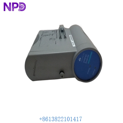
Description
- Model/Part Number: HONEYWELL 51304511-200
- Brand: Honeywell (USA)
- System Architecture: TDC 3000 / TotalPlant Solution (TPS) / Experion PKS (LEPI Architecture)
- Core Function: High-Density Axial High Level Analog Input (HLAI) processor board. It processes standard 4–20 mA and 1–5 V DC field signals from transmitters, isolation barriers, and smart field instruments into digital data for the Local Control Network (LCN) backplane.
- Condition: Brand New Surplus (Original factory authentic stock, never energized, pristine trace paths, complete with factory protective packaging)
- Product Type: High Level Analog Input (HLAI) Processing Module (Axial Form Factor)
- Operating Input Voltage: Derived directly from the card file backplane (+24 V DC and +5 V DC rails)
- Channel Density: 16 fully isolated analog input channels per board module
- Signal Input Configurations: Standard 4 to 20 mA DC current loops or 1 to 5 V DC voltage inputs
- A/D Converter Resolution: 16-bit successive approximation analog-to-digital converter array
- Common Mode Rejection Ratio (CMRR): >90 dB at 50/60 Hz line frequencies
- Normal Mode Rejection Ratio (NMRR): >45 dB at 50/60 Hz line frequencies
- Input Impedance: 250 \Omega precision internal loop shunt resistance (when strapped for current loop conversion)
- Galvanic Isolation Boundary: 1,500 V AC continuous channel-to-backplane logic isolation safety window
- Accuracy Window: ±0.05% of full-scale tracking envelope across the calibrated temperature range
- Power Dissipation: 4.8 W nominal operational processing consumption
- Form Factor Configuration: High-density axial processing board, optimized for vertical card file assemblies
- Conformal Coating: Full industrial-grade G3 hazardous-environment protection layer
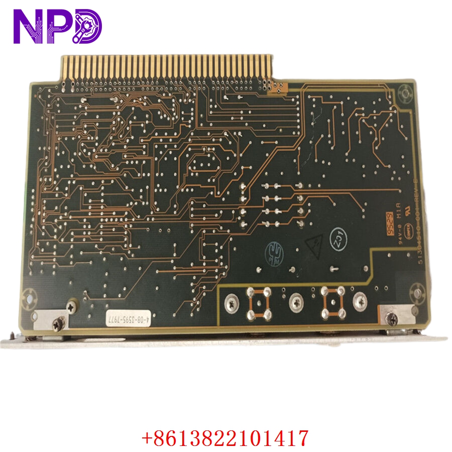
HONEYWELL 51304511-200
Installation & Configuration Guide
Pre-Installation Setup
⚠️ CRITICAL SAFETY WARNING:
- Coordinate a comprehensive process bypass window with the plant control room supervisor before replacing any I/O module. Removing an HLAI board instantly drops telemetry for 16 distinct loops, which can cause downstream control loops to shift to fallback values or trip the safety instrumented system.
- Ensure the associated field loops are safe. Put all automated control loops connected to this card into manual tracking mode at the operator station.
- Verify that your card file power supplies have steady voltage tolerances (+24 V DC loop supply must read between 22.8 V DC and 25.2 V DC).
- Required Tools & Gear:
- Grounded anti-static wrist strap connecting directly to the cabinet framework ground lug.
- Standard 4.0 mm flathead precision slot screwdriver for retaining screws and jumpers.
- Digital multimeter (such as a Fluke 289) with thin probe tips and an internal 0.01% accuracy tracking scale.
- Honeywell TDC 3000/Experion Control Builder configuration workspace running on an engineering workstation.
- Backup Procedures:
- Log into the Control Functions Builder environment, pull a complete parameters copy of the target I/O slot block mapping, and save an offline backup file (.xml or .ebk layout).
- Document the precise physical position of all hardware configuration jumpers (such as the current/voltage select straps) located along the card surface.
Old Module Removal
- Unload Configuration: Place the logical slot assignment for the target card into an “IDLE” or “OFFLINE” state using the engineering console to stop active communication polling.
- Disconnect Axial Connections: Loosen the top and bottom capture screws on the front-facing axial cable harness. Gently pull the connector plug straight forward to remove it from the board face, and secure the wiring bundle out of the way.
- Loosen Board Fasteners: Back out the upper and lower captive slot screws that secure the card body inside the card file chassis rails.
- Eject and Withdraw Card: Grip the card by its molded extraction tabs, pull them outward simultaneously to unseat the board from the backplane connectors, and slide the module straight forward out of the slot tracks. Place it flat on an ESD-safe workbench mat.
New Module Mounting and Configuration
- ESD Mitigation Check: Wear your grounded static wrist strap while extracting the replacement 51304511-200 board from its protective packaging. Do not touch the backplane edge fingers or open component traces.
- Replicate Jumper Topology: Look at your reference photos of the old board. Move the physical jumpers on the new board to match the exact configuration of the old one. These jumpers define whether each channel operates as a 4–20 mA current loop or a 1–5 V DC direct voltage input.
- Slide Into Slot Track: Align the edges of the card with the upper and lower plastic guide tracks in the target slot. Slide the board smoothly backward into the card file chassis until the edge connectors meet the backplane.
- Seat and Secure Fasteners: Push the injection levers inward to fully seat the board’s pins into the backplane. Tighten the upper and lower captive faceplate screws down snug (to roughly 0.5 N·m torque) to lock the module in place and establish a solid frame ground connection.
- Reconnect Axial Cable: Align the front-facing axial cable connector plug with the card socket interface. Push it firmly into place and tighten the capture screws down snug to prevent signal jitter from loose connections.
Post-Installation Verification Checklist
- [ ] Confirm that all onboard current/voltage configuration jumpers match the original card’s settings perfectly.
- [ ] Verify that the card sits flush in the card file and both retaining screws are tightened down snug.
- [ ] Check that the front-facing axial cable harness connector is fully seated and its capture screws are secured.
- [ ] Ensure that neighboring processing cards in the chassis have not been jarred out of place.
Loop Commissioning & Calibration Run
- Verify that the card file chassis power rails are stable.
- Observe the diagnostic status indicators on the module faceplate or the card file header:
- OK (Green): Solid green indicates the board’s internal core microcontrollers passed self-test diagnostics.
- FAIL (Red): Illuminates if the card detects a hardware malfunction, an incorrect jumper configuration, or an empty parameter block.
- Open your engineering workstation and access the Control Builder environment. Verify that the software recognizes the new module serial assembly code.
- Download your archived loop configuration profiles and tag assignments down to the card’s non-volatile memory. This action will clear any initial red FAIL light states.
- Place the slot back into an active “RUN” or “OK” operational state.
- Run a functional loop test: use an instrument simulator to inject a precise 12.00 mA intermediate reference signal into channel 1 at the terminal block. Confirm that the operator station HMI screen registers exactly 50.0% of the scaled measurement value without any signal offset or drift.
- Once all 16 channels pass loop testing, update your plant asset management records with the new board’s tracking details and return the control loops to automatic tracking mode.
Customer Cases & Industry Applications
Case 1: Chemical Center Distillation Column Telemetry Recovery
A large chemical processing center along the Yangtze River loop experienced a sudden loss of telemetry across 16 critical temperature and pressure tracking loops on a primary distillation column. The system log files flagged a major components hardware failure on a Honeywell TDC 3000 high-density 51304511-200 axial processing card. This failure left operators “flying blind” on vital column parameters, presenting an immediate safety risk and forcing them to place the process loop into a manual hold pattern.
The regional factory distribution network quoted a 14-week delivery timeline for a replacement module. To restore critical process visibility before a forced shutdown occurred, the facility’s maintenance group contacted us to check our ready surplus inventory for a 51304511-200 module. We pulled a brand-new surplus board from our shelves, verified its analog-to-digital converter circuits on our specialized TDC 3000 card file test rig, and shipped it via overnight air express that afternoon. The card arrived at the facility the next morning. Technicians completed the hardware swap, downloaded the system parameters configuration file, and restored full data telemetry to the control room within 24 hours of the initial failure.
Case 2: Fertilizer Plant Boiler Upgrades Optimization
During a scheduled maintenance turnaround at a large nitrogenous fertilizer plant, engineers found that several legacy analog input cards in a utility boiler control panel showed signs of internal heat stress and signal drift after years of continuous operation. The maintenance team decided to replace these worn components immediately during the shutdown window to prevent any unexpected processing faults during the upcoming production run.
[Legacy Analog Input Drift] ──> [Boiler Efficiency Drops & Trip Risks]
                                              │
              ┌───────────────────────────────┴───────────────────────────────┐
              ▼                                                               ▼
 [Option A: Full System Migration]                               [Option B: Direct Surplus Card Swap]
 • Cost: High capital expenditure (~$120,000)                    • Cost: ~75% savings vs complete upgrade path
 • Downtime: 5 days of wiring and software conversion            • Downtime: Completed in under 15 minutes per slot
 • Execution Risk: High loop recoding workload                   • Execution Risk: Drop-in match, zero wiring changes
The engineering group wanted an exact hardware match so they could reuse their existing, fully functional field wiring harnesses and axial cable assemblies without altering any system coding. They chose to source three brand-new surplus 51304511-200 modules from our inventory. The instrumentation crew completed the quick drop-in hardware swaps, transferred the channel configurations using the configuration utility, and re-engaged the system loops. This direct replacement eliminated the signal drift issues, preserved safety compliance, and allowed the plant to complete its maintenance turnaround right on schedule.
Frequently Asked Questions (FAQ)
Q1: What is the significance of the “-200” suffix on the part number 51304511-200?
A: The -200 suffix indicates the specific version and revision architecture of this high-density axial processing card. It denotes that the board features an industrial-grade conformal coating layer designed to protect the circuit traces against moisture, dust, and corrosive gases (such as hydrogen sulfide) in harsh industrial environments. It is fully backward compatible with older non-coated variants (like the -100 series) but provides significantly higher environmental reliability.
Q2: Does the module ship with pre-configured loop tags and signal ranges for our facility?
A: No, these modules do not ship with facility-specific parameters pre-loaded. The unit is provided as brand-new surplus hardware containing only its base factory bootloader and core system diagnostic utilities. Once you slide the board into your card file slot, you must use your Honeywell Control Builder software to download your project’s specific loop definitions, engineering units, and signal configuration maps.
Q3: How do you verify the accuracy of the analog-to-digital converters before shipping?
A: Our testing process goes far beyond a simple visual check. We place every surplus module into an authentic Honeywell TDC 3000 card file frame and connect it to a high-precision multi-point signal generator.
[TDC 3000 Test Card File] ──> [51304511-200 Module] <──> [Multi-Point Signal Generator]
                                                                  │
                                                                  ▼
                                                 [24-Hour Continuous Calibration Sweep]
We sweep precise signals (4.00 mA, 8.00 mA, 12.00 mA, 16.00 mA, and 20.00 mA) across all 16 channels simultaneously during a continuous 24-hour stress test. This process verifies that the 16-bit A/D conversion circuits maintain full linearity and read well within the strict ±0.05% accuracy window before the part leaves our facility.
Q4: Can I use this board for direct RTD or Thermocouple temperature sensor inputs?
A: No, the 51304511-200 is a High Level Analog Input (HLAI) card designed specifically to handle high-level signals like 4–20 mA current loops or 1–5 V DC voltage inputs. It cannot directly process low-level mV signals from thermocouples or resistance tracking from RTDs. To connect those sensor types, you must route the field lines through external signal conditioners/transmitters first to convert them to standard 4–20 mA signals, or use a dedicated low-level analog input card (such as an LLAI module) in your card file.
Q5: What does a solid red FAIL light on the front panel mean after installation?
A: A solid red fail light usually indicates that the module recognizes a mismatch or a fault state. Common causes include:
- The onboard hardware configuration jumpers do not match the channel parameters defined in the system software database.
- The module has not yet received its configuration download from the controller node.
- The front-facing axial cable harness is loose or disconnected, preventing proper interface mapping.
- The module was inserted into an incorrect or unassigned slot track inside the card file chassis.
Q6: What payment and shipping methods do you offer for urgent emergency plant shutdowns?
A: We accept international wire transfers (T/T), corporate credit cards, and standard letters of credit. For emergency repairs during an unplanned outage, send over a copy of your bank’s wire transfer confirmation slip. Our logistics team will immediately pull the part from our stock, complete our quality verification testing, and hand it off to an express air courier (like DHL or FedEx) to minimize your facility’s downtime.