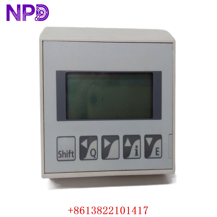
Description
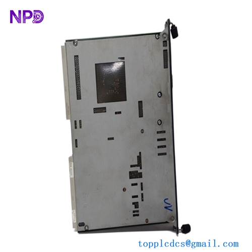
- Model: PCD4.D1XX (Specific P/N: 463665500)
- Brand: SAIA-Burgess (Switzerland)
- Series: PCD4 Process Control Device Series
- Core Function: 16-channel digital input module for interfacing 24V signals
- Product Type: Digital Input (DI) Module
- Key Specs: 16 Inputs 24 V DC Optocoupler Isolation
- Number of Channels: 16 digital inputs
- Input Voltage: 24 V DC (range 15…30 V DC)
- Input Current: Approx. 6 mA per channel at 24 V
- Input Filter: Integrated RC filter (typically 3 ms)
- Isolation: Galvanic isolation via optocouplers (between inputs and internal logic)
- Status Indicators: 16 LEDs on the front panel (one per channel)
- Connection: Plug-in screw terminal blocks or ribbon cable (depending on sub-version)
- Backplane Power: Approx. 10…20 mA from the 5V bus
- Operating Temp: 0 °C to +55 °C
SAIA PCD4.D1XX 463665500
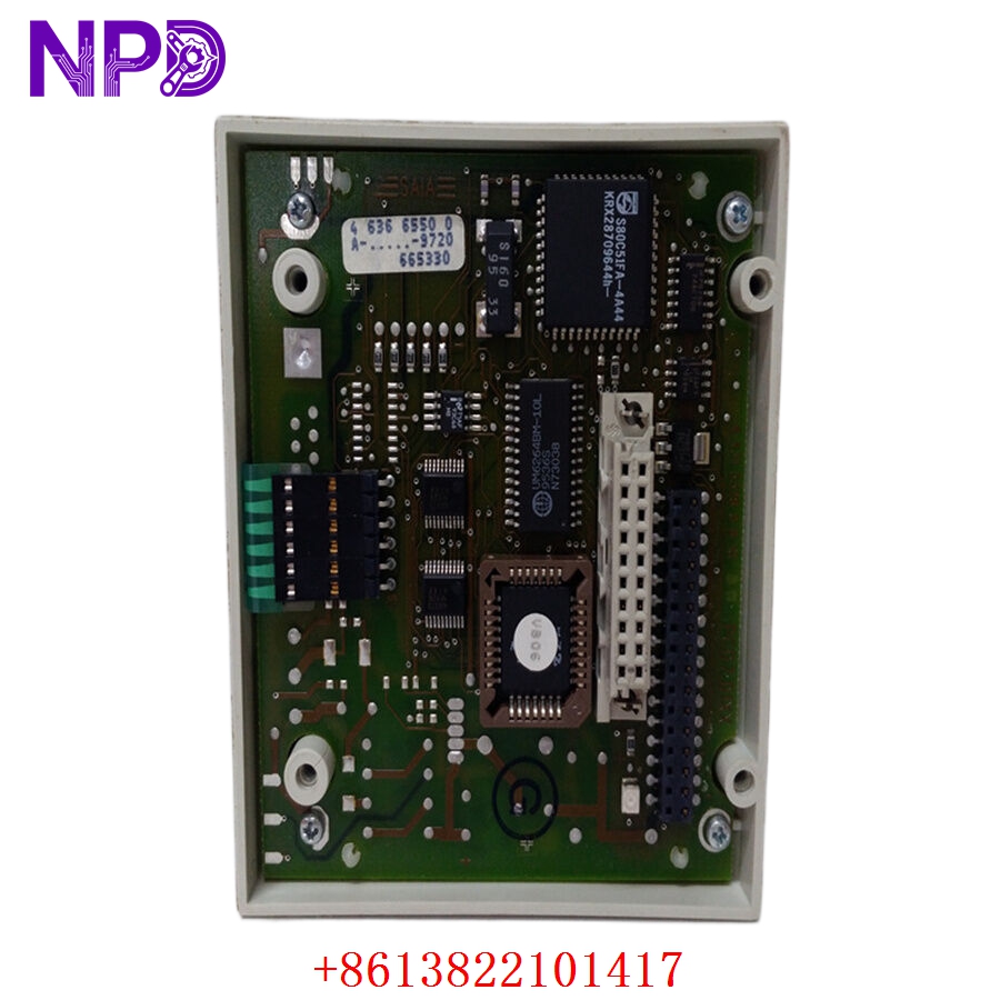
SAIA PCD4.D1XX 463665500
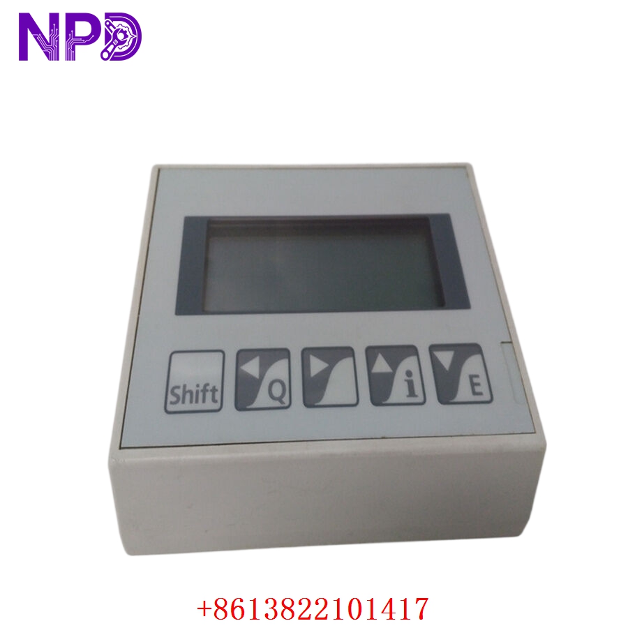
SAIA PCD4.D1XX 463665500
Application Scenarios & Pain Points
The SAIA PCD4 series is a classic, ultra-reliable PLC workhorse often found in European building automation, HVAC, and tunnel ventilation systems. Because the PCD4 is a mature product line, many facilities are struggling with “end-of-life” challenges. The PCD4.D1XX handles basic but critical feedback: limit switches, motor contactor statuses, and safety interlocks. When these modules fail—often due to voltage spikes on the 24V field side—entire sections of a building’s climate control or industrial process can go “blind,” leading to costly manual overrides or system lockouts.
Typical Application Scenarios:
- Building Management Systems (BMS)
Monitoring fire dampers, air handling unit (AHU) status, and pump feedback in large commercial complexes.
- Infrastructure – Tunnel Control
Collecting status signals from ventilation fans and emergency lighting systems where long-term stability is required.
- Food & Beverage Processing
Managing simple sequence logic for conveyors and packaging lines that haven’t been upgraded to newer PCD3 hardware.
- Water Treatment
Handling float switch inputs for tank level monitoring and valve position feedback.
Case Study: The “Cold” Data Center
Background:
A data center in Germany used a PCD4 system to manage its redundant cooling plant. During a power surge, the 24V field supply fluctuated, taking out several DI modules.
The Problem:
The system could no longer verify if the backup chillers had successfully started. Because the PCD4 is considered “legacy” by some vendors, the facility manager was told the lead time for a replacement was “indefinite,” risking a thermal shutdown of the servers.
The Solution:
We provided four PCD4.D1XX (463665500) units from our tested surplus stock. We verified the optocoupler integrity on every channel before shipping.
The Result:
The modules arrived within 48 hours. The maintenance team swapped the cards, and the DCS regained full visibility of the chiller plant. The facility avoided a catastrophic server outage for a fraction of the cost of a full PLC migration.
SOP Quality Transparency
Legacy modules require more than just a power-up test; they need a “physical” stress check to ensure they survive another decade.
- Connector & Trace Audit:
We inspect the backplane “gold fingers” for wear. If we see deep scratches or oxidation, we perform a professional cleaning and resurfacing. We also check for “leaking” electrolytic capacitors, which are common in modules of this age.
- Full-Channel Live Test:
We seat the PCD4.D1XX in a SAIA PCD4.Mxxx base rack.
- Signal Verification: We apply 24V DC to every one of the 16 channels and verify the corresponding LED lights up.
- Logic Verification: We monitor the PCD4 CPU’s internal register mapping to ensure the “1” bit is actually being registered in the software for every channel.
- Crosstalk Test: We trigger Channel 1 and ensure Channel 2 remains “0,” checking for internal short circuits.
- Input Filter Check:
We use a signal generator to verify that the RC filter is still within spec (approx. 3ms), ensuring the module correctly rejects high-frequency noise from field wiring.
- Packaging:
The module is wrapped in a silver ESD shielding bag and secured with anti-static “bubble-wrap” inside a rigid cardboard box to prevent physical damage to the front LEDs and rear connectors.
Technical “Pitfall” Guide
Replacing a SAIA PCD4 module is usually simple, but there are a few “traps” I’ve seen engineers fall into over the years.
- The “Common” Ground Trap ❗
The PCD4.D1XX inputs are often grouped. If you lose the “Common” (minus) connection to the module, all 16 channels will stop working simultaneously, even if the individual field wires have 24V.
The Fix: Check the terminal block’s common rail. If the whole module is “dark,” it’s almost always a missing 0V reference, not a dead module.
- Terminal Block Compatibility:
Depending on the specific 463665500 revision, the terminal blocks might be screw-type or tension-spring.
The Fix: Keep your old terminal blocks! If the new module doesn’t come with them, the old ones are usually interchangeable. Make sure the pins are clean before plugging them into the new card.
- Input Voltage Thresholds ❗
SAIA inputs typically “turn on” at about 15V. If your field wiring has significant voltage drop (long cable runs), you might measure 12V at the module. The LED might glow dimly, but the PLC will register it as “OFF.”
The Fix: Measure the voltage at the module terminals while the field switch is closed. If it’s below 18V, you have a wiring/power supply issue, not a module fault.
- Hot-Swapping Caution:
While the PCD4 is robust, it was designed before “Active Backplanes” became standard.
The Fix: Power down the rack before pulling or inserting the PCD4.D1XX. Swapping it while the 5V bus is live can cause a spike that corrupts the CPU’s memory or damages the backplane interface.
Troubleshooting Quick Reference
| Symptom | Possible Cause | Relevance | Quick Check | Recommendation |
| All 16 LEDs Off | Missing Common / Power | ✅ High | Measure 24V between Input and Common. | Check the 0V/Ground rail. |
| LED is On, PLC is Off | Backplane Interface | ✅ High | Check if other modules in the rack work. | Reseat the module; check backplane pins. |
| Input Flickers | Electrical Noise / EMI | ⚠️ Med | Check if the field cable is shielded. | Ensure shield is grounded at one end. |
| LED Dim / Erratic | Low Voltage Drop | ✅ High | Measure voltage at the terminal (should be >15V). | Check power supply or wire length. |
| Single Channel Dead | Optocoupler Failure | ✅ High | Swap the wire to a known good channel. | Replace Module. |
Pro Tip: If you see the “FAIL” LED on the CPU after inserting the module, it usually means the module isn’t seated correctly in the rack. Pull it out, clean the gold pins with an eraser (the soft white kind), blow out the rack slot with air, and try again. 90% of the time, that fixes it!