
Description
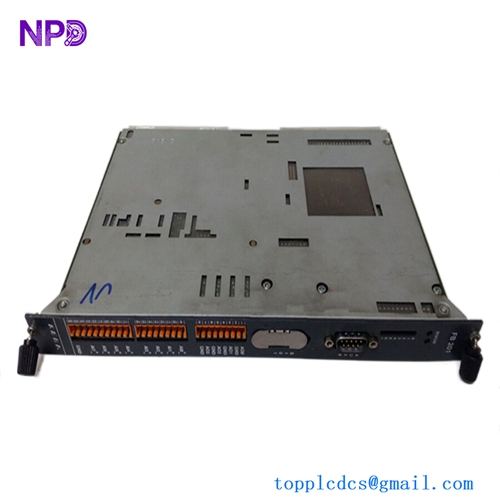
The Techcross AIM-V-2006151 is a marine-certified control interface module designed specifically for integration within Techcross Electro-Cleen™ Ballast Water Management Systems (BWMS). Operating as a high-performance data parsing and distribution node, this module manages real-time communication between the main ECS (Electro-Cleen System) control computers, power distribution panels, and physical electrolysis units. Built to operate in demanding marine environments, the AIM-V-2006151 provides high noise immunity and deterministic data processing to ensure the safe, compliant, and efficient treatment of shipboard ballast water.

⚙️ Technical Specifications
- Part Number/Model: AIM-V-2006151
- Dimensions: 168mm x 110mm x 45mm
- Weight: 0.65 kg
- Origin: South Korea
- Supply Voltage: 24V DC nominal (18V to 32V DC operational window)
- Isolation Rating: Optocoupler isolation up to 2000V RMS for field-side signal protection
- Communication Interface: Dual RS-485 serial channels, high-speed CAN bus, and standard industrial Ethernet ports
- Ingress Protection: IP20 (Designed for enclosed control cabinet installation)
🚀 Application Fields
- Ballast Water Management Systems (BWMS): Core signal routing and protocol conversion for Techcross Electro-Cleen™ marine installations.
- Electrolysis Unit Monitoring: Real-time interfacing with current, voltage, and temperature sensors on active electrolysis chambers.
- Marine Environmental Automation: Coordinating automatic valve sequencing and dosing telemetry based on salinity and Trojan Horse sensor readings during ballasting/de-ballasting operations.
- Ship-to-Shore Telemetry Systems: Aggregating data parameters for mandatory voyage compliance logs and ballast treatment verification reports.
📖 Product Instructions
- Cabinet Mounting: Snap the AIM-V-2006151 module onto a standard TS35 DIN rail within a centralized, climate-controlled BWMS control enclosure. Ensure the integrated metal grounding clip on the back of the module makes firm contact with an unpainted section of the DIN rail.
- Signal Interface Hookup: Connect the twisted-pair communication cables to the pluggable terminal block interfaces. Separate low-voltage sensor transmission lines from the high-amperage cables running to the electrolysis power rectifiers.
- Address & Protocol Allocation: Set the module station ID using the onboard configuration dials (or web-management interface) to match the corresponding controller map in the system topology.
✅ Initial Startup Checklist
- Verify that the 24V DC auxiliary power supply delivers stable voltage and matches the polarity markings on the module housing.
- Confirm that all external terminal blocks are pushed flat into their sockets and the locking ears are secure.
- Energize the system and confirm that the primary “PWR” (Power) LED illuminates steady green and the “RUN” indicator flashes normally.
- Check the main BWMS touch panel (HMI) to verify that data variables from the AIM module are populating without generating communication timeout alarms.
🛠️ Maintenance & Care
- Terminal Retightening: Inspect the terminal screws every six months and re-torque if necessary to counteract loosening caused by shipboard mechanical vibration.
- Surface Cleaning: Keep the ventilation slots clear of dust, salt residue, or moisture. Clean the external plastic housing exclusively with a dry, anti-static cloth.
- Firmware Lifecycle Upgrades: Check the running firmware version against Techcross service bulletins during annual classification society surveys to ensure full compliance with updated IMO and USCG data logging regulations.
⚠️ Safety Precautions
- Electrolysis Current Hazard: Never alter configuration pins or plug/unplug communication lines while the high-voltage electrolysis power rectifiers are energized.
- Strict Power Off Compliance: Ensure the main control circuit breaker is locked out and tagged out before unmounting or servicing the module card hardware.
- Static Charge Safeguards: Always use a grounded ESD wrist strap when handling the unit to shield internal surface-mount microchips from static breakdown.
🔍 Troubleshooting & FAQ
- Q: The display workstation reports a “Communication Disconnect Error” on the node assigned to this module.
- A: This indicates a network fault. Inspect the RS-485 or CAN bus twisted pairs for physical breaks, verify that the 120-ohm termination resistors are installed at the physical ends of the line, and check for high-frequency noise interference from nearby rectifiers.
- Q: The power light is active, but the “ERR” (Error) LED lights up solid red.
- A: A solid red error light typically indicates a hardware self-test failure or a corrupted configuration file. Cycle the power to trigger a fresh boot; if the error persists, reload the original system configuration matrix via the service port.
- Q: Can this interface module be swapped without stopping active ballast operations?
- A: No. Removing this module breaks the communication loop between the control system and the treatment elements, which will cause an immediate emergency stop (ESD) of the entire BWMS to prevent untreated water from being moved. All replacements must be performed while the system is offline.