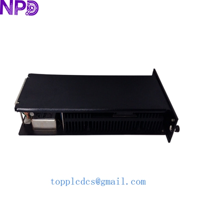

Description
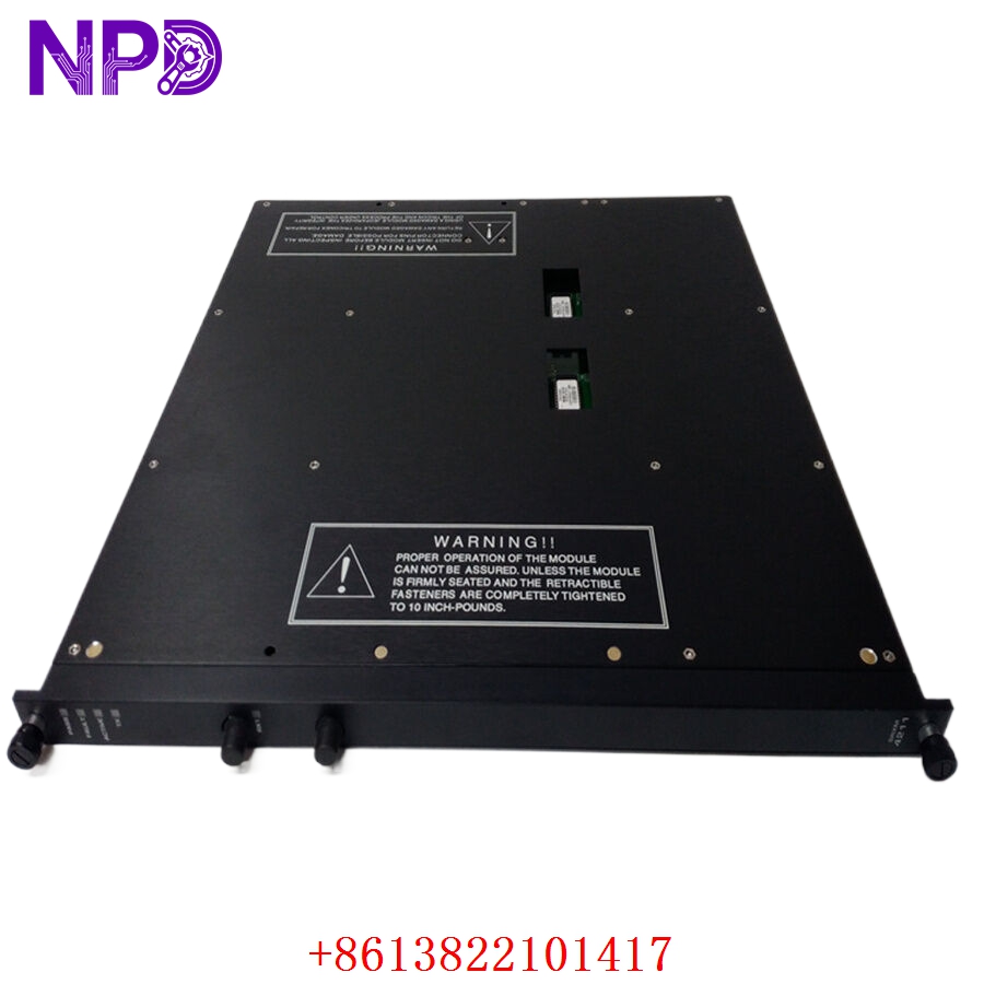
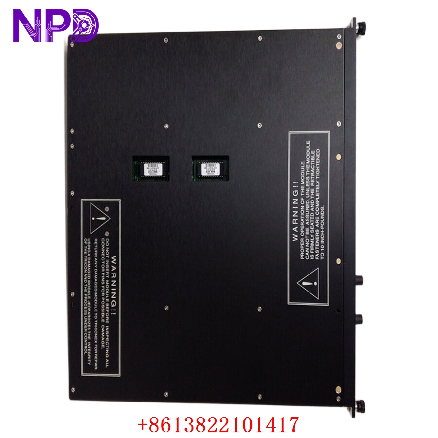
The TRICONEX 4211 is a specialized Remote Extender Module (RXM) designed to facilitate communication between a primary Tricon chassis and remote I/O expansion racks. This TRICONEX 4211 module is essential for large-scale Safety Instrumented Systems (SIS) where field devices are distributed across significant distances, allowing for the extension of the Triple Modular Redundant (TMR) backplane over fiber optic or copper links. By maintaining the integrity of the TMR architecture across distributed locations, the 4211 ensures that remote I/O signals are processed with the same level of fault tolerance and voting logic as those in the main processor chassis.
Technical Specifications
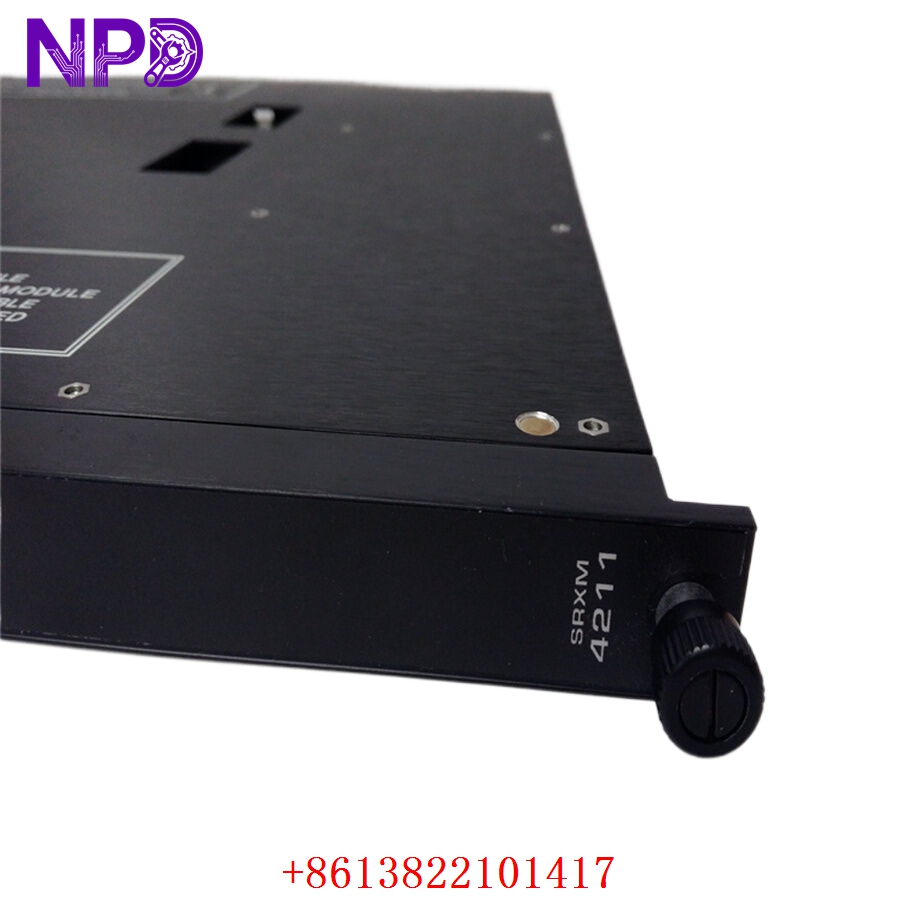
- Model Number: 4211
- Module Type: Remote Extender (RXM) / Interface Module
- Redundancy: Triple Modular Redundant (TMR)
- Communication Media: Fiber Optic (typically Multimode)
- Maximum Distance: Up to 2 kilometers (1.2 miles) depending on cable quality
- Data Rate: High-speed proprietary I/O bus extension
- Isolation: Complete galvanic and optical isolation between chassis
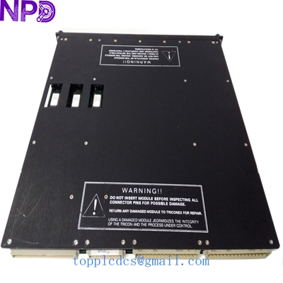
- Diagnostic LEDs: Pass, Fault, Active, and Link Status
- Operating Temperature: 0°C to +60°C
- Power Consumption: Approximately 5W The 4211 functions as a transparent bridge, allowing the main processors to “see” remote I/O modules as if they were residing in the local rack, effectively eliminating the need for complex communication programming between separate controllers.
TRICONEX 4211
TRICONEX 4211
TRICONEX 4211
Model Comparison
The TRICONEX 4211 is primarily distinguished from the 4210 or 4201 series by its support for fiber optic connectivity and extended distance capabilities. While the 4200 series modules are often used for short-range electrical extensions within the same cabinet or adjacent racks, the 4211 is the standard choice for inter-building or site-wide distribution. Unlike standard Ethernet bridges, the 4211 maintains the synchronized TMR timing required for SIL 3 safety loops, providing hardware-level synchronization that software-based bridges cannot replicate.
Operational Tips
- Fiber Integrity: Ensure that fiber optic connectors (typically ST or SC) are cleaned with specialized lint-free tools before insertion, as even microscopic dust can cause signal attenuation and bus errors.
- Matched Pairs: RXM modules must be installed in matched sets; a 4211 in the primary chassis must communicate with a corresponding 4211 (or compatible RXM) in the remote chassis to establish the link.
- Bend Radius: Observe strict adherence to the minimum bend radius of the fiber optic cables connecting the modules to prevent “micro-fractures” that lead to intermittent communication drops.
- Redundancy Testing: Periodically check the “Active” status LEDs on all three legs (A, B, and C) of the TMR link; since the system can run on two legs, a single leg failure in the 4211 might go unnoticed without routine visual or software audits.