
⚙️ Product Introduction
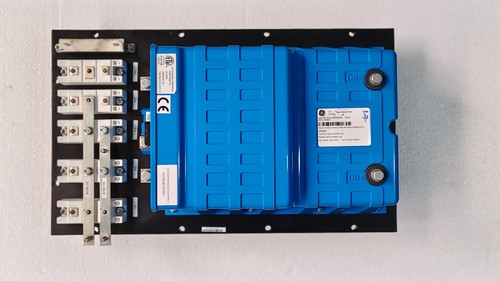
The GENERAL ELECTRIC 151X1233DB02SA02 Rev A is a GE Energy 151X-series power conversion assembly used in wind turbine pitch-control applications. Available technical references identify it specifically as a Rev A Pitch Converter, with a continuous output rating of 10 kW. The assembly includes a converter/diode section, DB+/DB− connections, S1/S2 bus connectors, and positive/negative screw terminals.
The part is associated with GE wind-energy control hardware and is intended for integration into the appropriate GE pitch-control system rather than general-purpose standalone power conversion. A current product listing also identifies the unit as a GE Energy converter and gives a nominal current rating of 100 A.
📋 Product Datasheet
| Parameter | Specification |
|---|---|
| Brand | General Electric / GE Energy |
| Model | 151X1233DB02SA02 |
| Series | 151X Boards and Modules |
| Product Name | Rev A Pitch Converter |
| Functional Type | Power / Pitch Converter |
| Revision | Rev A |
| Continuous Output Rating | 10 kW |
| Nominal Current Rating | 100 A |
| Hardware Revision | CAA / Rev A |
| Year Reference | 2017 |
Technical references identify the 151X1233DB02SA02 as a GE Energy Rev A Pitch Converter and specify 10 kW continuous output. The 100 A nominal current figure is reported by the product identification listing.
Condition: The exact condition depends on the individual unit being supplied. New/open-box and surplus examples are available in the replacement market.
Country of Origin: Published seller listings are inconsistent, with some identifying China and other industrial references identifying USA. Therefore, the actual nameplate or manufacturing label should be used to determine the country of origin for a specific unit.
🔧 Operating Standards & How to Use
Before installation, verify that the converter is the exact hardware revision required by the GE pitch-control system.
🔹 Confirm the complete part number and Rev A identification.
🔹 Inspect the converter/diode assembly, terminals, connectors, mounting backplane, and insulation.
🔹 Verify the DC bus and power connections against the equipment wiring documentation.
🔹 Check DB+/DB− polarity carefully before energization.
🔹 Verify S1 and S2 bus connections.
🔹 Confirm the connected pitch-control hardware is compatible with the converter.
🔹 Check grounding and protective bonding.
🔹 Inspect all power terminals for loose connections or corrosion.
🔹 Apply power only after the complete pitch-control circuit has been checked.
The converter should be treated as a system-level industrial power component. Do not connect it to an arbitrary AC or DC source simply because the physical connectors appear compatible.
▶️ Startup Sequence
- 🔍 Inspect the converter and verify the model/revision.
- 🔌 Confirm all power and control wiring.
- ⚡ Verify incoming supply voltage according to the equipment design.
- 🔩 Check DB+/DB− polarity and terminal tightness.
- 🧩 Verify S1/S2 connections and associated control hardware.
- 🛡️ Confirm protective grounding and circuit protection.
- ▶️ Energize the system according to the turbine manufacturer’s commissioning procedure.
- 📊 Monitor converter output, alarms, temperature, and pitch-system feedback.
- 🧪 Perform a controlled functional test before returning the turbine to normal operation.
⏹️ Shutdown Sequence
- Stop the turbine or place the pitch-control system into its approved service/maintenance state.
- Remove the normal operating command.
- Allow the pitch system to reach its safe position.
- Isolate the applicable power source.
- Apply lockout/tagout procedures.
- Verify that hazardous voltage has been removed.
- Allow DC-link or stored electrical energy to discharge according to the equipment procedure.
- Test for absence of voltage before touching the converter.
⚠️ Do not open or service the converter immediately after shutdown unless the manufacturer’s discharge and electrical-safety requirements have been satisfied.
📘 Product Usage Instructions
The 151X1233DB02SA02 is intended to operate as part of a GE pitch-control power system. Its job is not simply to provide generic DC power; it forms part of the electrical path used by the pitch system.
During operation, the converter works with the associated control electronics, power connections, and pitch-drive equipment. The correct configuration depends on the turbine platform and cabinet in which the module is installed.
For replacement work, compare:
• Complete part number
• Revision level
• Connector arrangement
• Terminal layout
• Converter/diode assembly
• Control-system compatibility
• Software/firmware requirements
• Mechanical mounting arrangement
Do not substitute a visually similar 151X-series board without checking the system documentation.
🛠️ Installation & Maintenance Notes
🔹 Keep the converter dry and free from conductive dust.
🔹 Use appropriate ESD protection when handling electronic assemblies.
🔹 Do not place tools or loose metal objects across DC terminals.
🔹 Inspect the power terminals periodically for discoloration or heat damage.
🔹 Check connectors for oxidation or mechanical damage.
🔹 Record the hardware revision before replacement.
🔹 Keep the original module configuration documented before removing it.
🔹 After replacement, perform system-level commissioning rather than assuming the converter is operational simply because it powers up.
❓ Common Questions & Answers
Q: What is the 151X1233DB02SA02?
A: It is a GE Energy 151X-series Rev A Pitch Converter used in GE wind-turbine pitch-control hardware.
Q: What is its continuous output rating?
A: The technical reference lists a 10 kW continuous output rating.
Q: Is it a general-purpose industrial converter?
A: No. It is specifically identified as a pitch converter, so compatibility with the intended GE pitch-control system should be verified before use.
Q: What is the revision?
A: The requested unit is Rev A, with the complete part number 151X1233DB02SA02.
Q: What connections are provided?
A: Technical documentation references DB+/DB− poles, an S1/S2 bus connection, and positive/negative screw terminals.
Q: Is 151X1233DB02SA02 still available?
A: It appears primarily through industrial replacement, surplus, and open-box channels rather than ordinary current-product distribution.
Q: Can I replace another GE 151X converter with this unit?
A: Not automatically. The complete part number, revision, electrical characteristics, connectors, and system application must match.
Q: Does the unit require special commissioning?
A: Yes. Because it is part of a wind-turbine pitch-control system, commissioning should be performed according to the applicable GE system documentation and site safety procedures.
⭐ Recommended GE 151X Series Models
- 151X1233DB01SA01 — Pitch Converter / related 151X configuration
- 151X1233DB02SA02 — Rev A Pitch Converter
- 151X1233DB01SA02 — 151X-series converter configuration
- 151X1233DB02SA01 — 151X-series converter configuration
- 151X1233DB03SA02 — 151X-series power conversion configuration
- 151X1233DB03SA01 — 151X-series converter configuration
- 151X1233DB04SA02 — 151X-series converter configuration
- 151X1233DB04SA01 — 151X-series converter configuration
- 151X1233DB05SA02 — 151X-series converter configuration
- 151X1233DB05SA01 — 151X-series converter configuration
⚠️ The models above should be treated as related 151X-series references rather than confirmed drop-in replacements. Exact interchangeability must be established from the turbine’s electrical drawings and GE part-number documentation. The 151X1233DB02SA02 itself is documented as a specific Rev A pitch converter.
📦 Replacement Purchasing Tip
For an industrial replacement purchase, provide the seller with the complete identification:
GE Energy | 151X1233DB02SA02 | Rev A | Pitch Converter
Also request clear photographs of the nameplate, PCB revision, terminals, connectors, and converter/diode assembly before shipment. This is especially useful for surplus stock because externally similar GE assemblies can have different revisions or applications.


