
Description
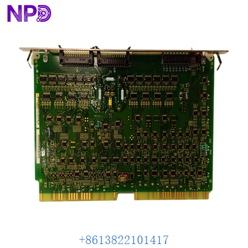
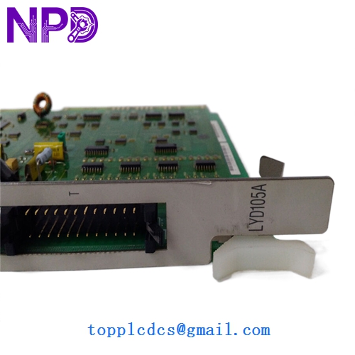
- Model: Hitachi LYD105A
- Brand: Hitachi
- Series: HIDIC-H Series PLC (Legacy)
- Core Function: 16-channel relay output for controlling external devices
- Product Type: Discrete Relay Output Module
- Key Specs: 16 Points 240 V AC / 24 V DC Independent Commons
- Output Channels: 16 independent relay contacts
- Rated Load Voltage: 240 V AC (max) / 24 V DC (max)
- Max Load Current: Typically 2 A per point (max 8 A per common)
- Response Time: < 10 ms (ON) / < 12 ms (OFF)
- Isolation: Optical/Relay isolation between internal logic and field side
- Indicators: Front-panel LED status for each of the 16 channels
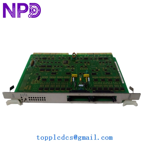
- Terminal Type: Detachable screw-terminal block for easy maintenance
- External Power: Requires 24 V DC for internal relay coil operation
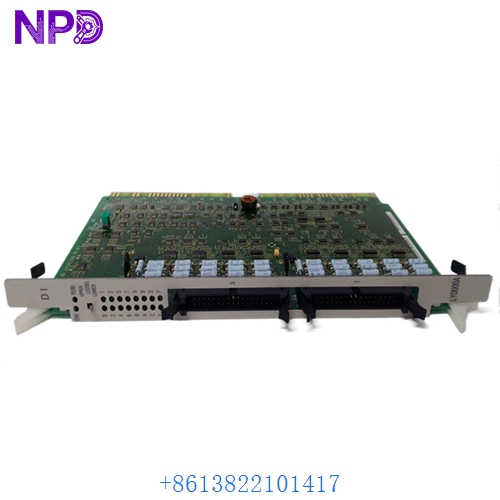
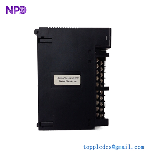
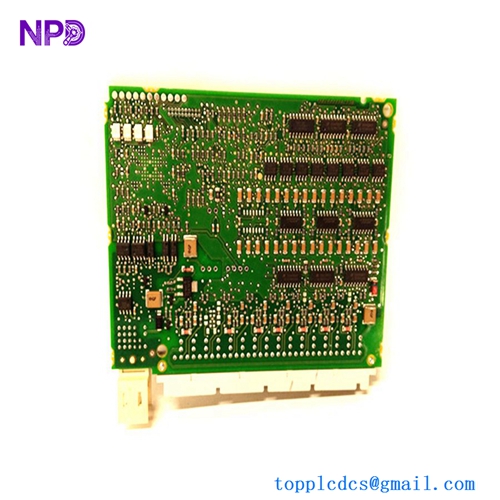
HITACHI LYD105A
HITACHI LYD105A
HITACHI LYD105A
Application Scenarios & Pain Points
The Hitachi LYD105A is a staple of the HIDIC-H series PLC systems, often used in heavy industrial environments like steel mills and automotive assembly lines. Since it uses mechanical relays, it is perfect for switching diverse loads, from small pilot lights to large motor starters. However, because relays have a finite mechanical life, the LYD105A is one of the most common “wear parts” in an aging Hitachi system. Once a relay contact welds or the internal coil burns out, that specific channel is lost, often halting a critical piece of machinery.
Typical Application Scenarios:
- Conveyor System Management Triggering motor contactors and solenoid brakes in material handling lines.
- HVAC & Pump Control Switching 120/240 V AC fans and pumps in industrial cooling systems.
- Alarm & Annunciator Panels Driving high-voltage horns, beacons, and remote indicator lamps.
- Legacy Machine Retrofits Serving as the primary output interface for machines still running on HIDIC-H series logic.
Case Study: The “Stuck” Solenoid
Background: A manufacturing facility in Southeast Asia used a HIDIC-H series PLC to control a hydraulic press. One day, the press failed to retract, even though the PLC logic commanded it to.
Problem: Investigation showed that the LYD105A module had its “Channel 4” LED off, but the physical relay was stuck in the ON position. The mechanical contacts had welded together due to years of switching an inductive solenoid load without an external surge suppressor.
Solution: We provided an emergency replacement LYD105A. To prevent a recurrence, we recommended installing an RC snubber across the solenoid coil.
Result:
- Production Restored: The press was back in operation within the shift.
- System Longevity: By adding external protection, the new module’s relay life was extended significantly.
- Engineer’s Insight: “With the LYD105A, if you hear the relay ‘clicking’ but don’t see power on the field side, the contacts are carbonized. If it doesn’t click but the LED is ON, the coil is dead. In either case, the module needs replacement.”
Compatible Replacement Models
The HIDIC-H series has several output variations. The LYD105A is the standard relay version.
| Original Model | Replacement Model | Compatibility | Note |
|---|---|---|---|
| LYD105A | LYD105A | ✅ Exact Match | Standard 16-pt Relay Output. |
| LYD105A | LYD105 | ⚠️ Physical | Earlier version; verify terminal block compatibility. |
| LYD105A | LYD101 | ❌ Incompatible | LYD101 is a Transistor (DC) output; cannot switch AC. |
Troubleshooting Quick Reference
| Symptom | Possible Cause | Relation | Quick Check | Action |
|---|---|---|---|---|
| LED is ON, but no output | Blown Common Fuse | ✅ High | Check continuity across the field-side common terminal. | Replace fuse or check field power. |
| Output stays ON always | Welded Contact | ✅ High | Disconnect field wires; check continuity with PLC OFF. | Replace LYD105A module. |
| No LEDs or Outputs | 24V Logic Power | ✅ High | Check external 24V DC supply to the module. | Restore power to the terminal block. |
| Erratic “Chattering” | Low Control Voltage | ⚠️ Med | Measure the 24V DC supply under load. | Upgrade or fix the power supply. |
❗ Pro Tip: Terminal Blocks
The LYD105A usually features a removable terminal block. When replacing the module, you don’t need to disconnect every single wire. Simply unscrew the mounting screws on the terminal block, pull it off, swap the module, and plug the block back in. This reduces the risk of wiring errors and cuts downtime from an hour to five minutes.
Handling & Installation:
- Safety: Always turn off field power before removing the terminal block, as 240 V AC may be present on the screw terminals.
- Load Limits: Do not exceed the total common current (8 A). If you are switching 16 high-draw devices, split the power across multiple commons.
- Mechanical Vibration: Ensure the module is securely latched into the rack. Loose connections on the backplane can cause the CPU to fault with an “I/O Error.”