
Description
- Product Parameters
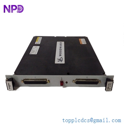
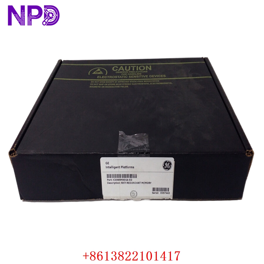
- Model Designation: WOODWARD 5466-253
- Module Type: Discrete I/O Module (High Density)
- System Compatibility: MicroNet TMR (Triple Modular Redundant) / MicroNet Simplex
- Input Channels: 48 Discrete Inputs
- Input Voltage Range: 18–32 VDC (24 VDC Nominal)
- Power Requirement: +5 VDC, 1.5 A Max (sourced from backplane)
- Response Time: < 1 ms (Input to Processor)
- Isolation: 500 Vrms to Chassis; 500 Vrms to Control Logic
- Operating Temperature: -40°C to +70°C (-40°F to +158°F)
- Certification: CE, UL/cUL Listed, Class I Div 2 Groups A, B, C, D
The Woodward 5466-253 is a high-density discrete input module engineered for the MicroNet control platform, providing 48 independent channels for monitoring critical dry contact or voltage-sensing field devices. Designed for high-reliability applications such as steam turbine or gas turbine control, this module integrates seamlessly into TMR architectures to ensure fault-tolerant operation and millisecond-level signal processing in harsh industrial environments.
Distinctions from Similar Models
- Channel Density: While many MicroNet modules offer 24 channels, the 5466-253 provides 48 inputs, significantly reducing rack space requirements for large-scale I/O deployments.
- TMR Architecture: Specifically optimized for Triple Modular Redundant systems, allowing for voting logic that is more robust than the standard 5466-series Simplex variants.
- Enhanced Isolation: Features superior galvanic isolation between field-side inputs and the control logic backplane compared to legacy I/O cards, preventing surge propagation.
Product Operation Guidelines
- Backplane Seating: Ensure the module is fully seated in the MicroNet chassis and the securing screws are tightened to maintain a consistent connection to the +5V power bus.
- Field Wiring: Use dedicated terminal blocks (FTMs) for all 48 channels to simplify troubleshooting and ensure that signal shielding is properly grounded at the entry point.
- Redundancy Mapping: When used in a TMR configuration, verify that the application software correctly maps the inputs across all three CPUs to utilize the system’s fault-masking capabilities.
- Contact Debouncing: Although the hardware responds in < 1ms, implement appropriate software debouncing timers to filter out mechanical contact bounce from field switches.