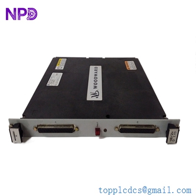
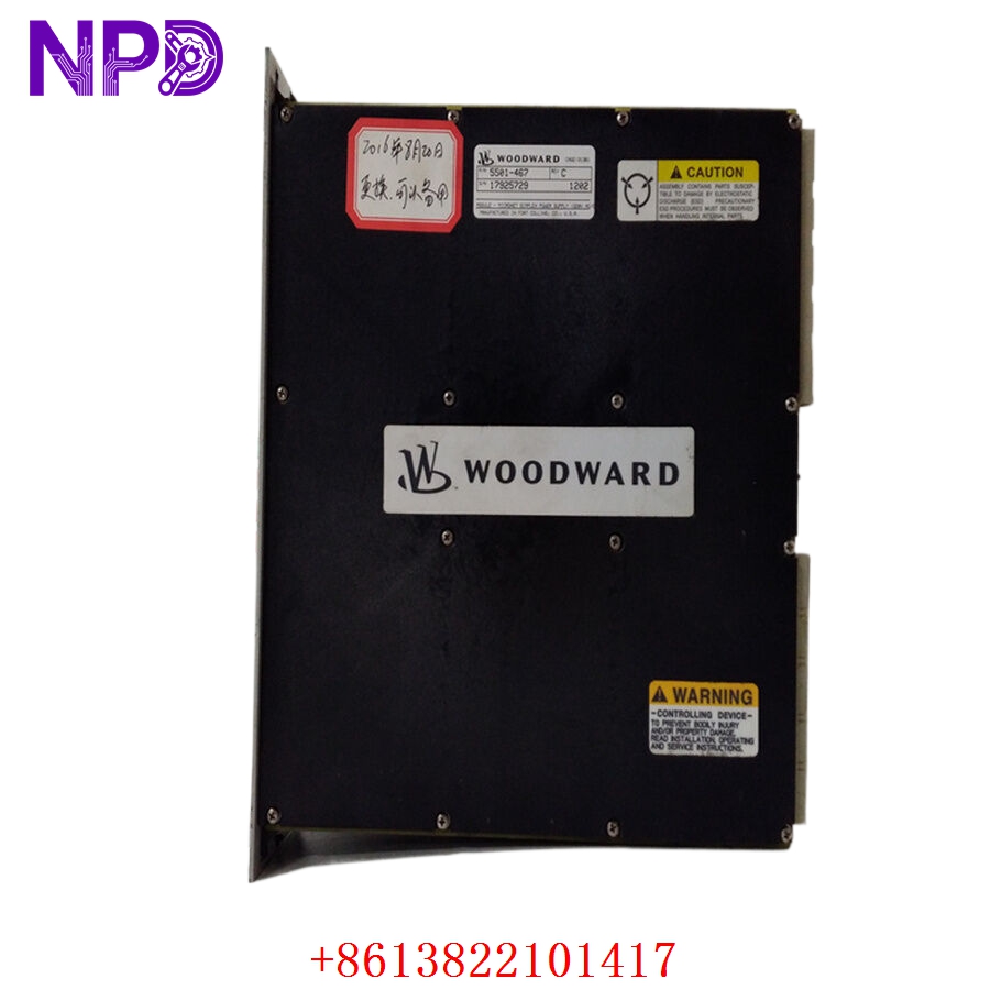
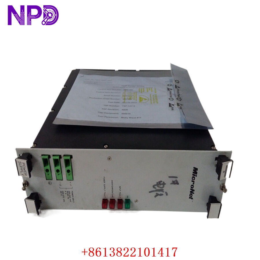
Description
- Model: WOODWARD 5501-467
- Brand: Woodward (USA)
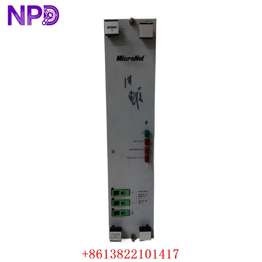
- Series: MicroNet / MicroNet Plus Digital Control System
- Core Function: Main CPU/Transceiver communication processing block for steam, gas, and hydro turbine control systems
- Condition: Brand New Surplus (Original authentic stock, never energized, immaculate factory condition)
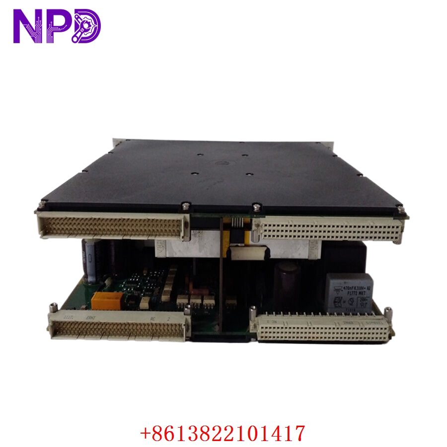
- Product Type: CPU / Transceiver Main Control Module
- Key Specs: VMEbus architecture compliance, high-speed remote I/O network links, 5 V DC logic rail integration
- Operating Operating Voltage: 5 V DC logic rail supply via the backplane assembly (±5% tolerance window)
- Current Consumption: 3.5 A nominal logic operating load
- Processor Framework: High-performance embedded controller with integrated real-time clock array
- Backplane Architecture: Standard VME64 compliant parallel bus structure
- Communication Interface: Dedicated high-speed differential serial transceivers for remote I/O chassis extension
- Data Transfer Rate: Up to 25 Mbps across dedicated remote I/O network lines
- Isolation Boundary: 500 V AC galvanic isolation between communication channels and core processing logic
- Operating Temperature Range: 0°C to +60°C ambient air envelope
- Storage Temperature Envelope: -40°C to +85°C maximum limits
- Humidity Tolerance: 5% to 95% relative humidity (RH, non-condensing)
- Conformal Coating: Full industrial-grade PCB coating for harsh atmospheric protection
- Diagnostics: Real-time backplane voltage checking, system watchdog timers, and localized fault status LEDs
WOODWARD 5501-467
WOODWARD 5501-467
WOODWARD 5501-467
WOODWARD 5501-467
WOODWARD 5501-467
Installation & Configuration Guide
Pre-Installation Setup
⚠️ CRITICAL SAFETY WARNING:
- Coordinate a formal shutdown window with the turbine control operations room before accessing the active control rack.
- Ensure all high-voltage actuation loop supplies and trip circuit outputs are isolated and tagged out.
- Verify that the system’s redundant controller track (if utilizing a MicroNet TMR configuration) is stable and holding the active process load.
- Wait for the cabinet cooling fans to run for a few minutes if the rack was running hot, ensuring components are safe to handle.
- Required Tools & Gear:
- Grounded anti-static wrist strap connecting directly to the cabinet steel frame.
- Standard 4.5 mm flathead screwdriver for chassis latch screws.
- Fiber optic cleaning kit and specialized clean air canister (if optical extensions are present).
- Digital multimeter (such as a Fluke 117) with thin probe tips.
- Handheld camera or phone for documenting the old module’s slot placement and physical labels.
- Backup Procedures:
- Open the Woodward AppManager or Coder software tool and pull an archive copy of the active application code file (.wrd or .scp file).
- Note the exact slot assignment of the module within the primary VME chassis rail.
- Document all physical hardware selector switches, jumper configurations, and network connection strings on the front plate.
Old Module Removal
- Unplug Communication Cabling: Disconnect the dedicated remote I/O network cords or serial links from the front panel ports. Label each line as “Main Link” or “Redundant Link” to ensure exact matching later.
- Loosen Faceplate Screws: Back out the captive retaining screws located at the top and bottom edges of the module faceplate using your flathead screwdriver.
- Eject the Module: Unlatch the injection/ejection handles on the front panel. Press the levers outward simultaneously to break the backplane pin friction bond.
- Slide out cleanly: Draw the module straight forward along the chassis guide rails. Hold the assembly by its structural metal frame and immediately place it down flat onto an ESD-safe workbench mat.
New Module Mounting and Configuration
- ESD Mitigation: Keep your grounded wrist strap attached while removing the new module from its silver anti-static shielding pouch. Do not slide the component surface across rough structures.
- Match Hardware Topography: Look closely at your reference photos of the old board. Replicate the exact positions of any physical jumpers or rotary node selection switches on the replacement card.
- Chassis Alignment: Align the top and bottom edge tracks of the new card with the empty slot channels in the MicroNet frame. Slide the module smoothly backward until the rear pins meet the backplane.
- Lock in Position: Press the front injection levers inward simultaneously until they snap shut, seating the board firmly into the VME backplane pins. Tighten the top and bottom captive faceplate screws to 0.8 N·m to secure a solid frame ground link.
- Reconnect Network Cables: Plug your communication lines back into their matching front ports, ensuring all retaining clips or thumb screws are fully secured.
Post-Installation Verification Checklist
- [ ] Confirm that both injection/ejection levers are fully closed and latched.
- [ ] Verify faceplate grounding screws are threaded down snug.
- [ ] Check that all communication lines match their original port mappings exactly.
- [ ] Verify that neighboring cards in the rack have not been jarred or partially unseated.
Power-Up & Loop Commissioning
- Re-apply power to the primary MicroNet chassis power supply loop.
- Observe the front-facing LED diagnostics assembly array:
- CPU/RUN: Solid green, indicating the internal core initialization completed successfully.
- TX/RX: Flashing amber or green, tracking rapid data packet exchanges on the transceiver links.
- SYS FAULT: A solid red light indicates a failed boot verification check or an incompatible firmware footprint.
- Launch Woodward AppManager on your laptop. Scan the local bus network to confirm the node address matches your configuration map.
- Use the application manager interface to verify the current operating system and network firmware version matches your site requirements. If necessary, load the correct runtime block to align with your facility’s software standards.
- Download your archived turbine control parameter application file back down to the flash storage on the board.
- Run a diagnostic cycle loop to check the remote I/O link paths. Confirm that the master system reads all distant temperature and pressure inputs smoothly without signal jitter.
- Once the system operates cleanly for 30 minutes with zero bus timeout alarms logged on the master HMI, update your maintenance logs and clear the turbine loop for automated service.
Customer Cases & Industry Applications
Case 1: Cogeneration Plant Steam Turbine Governor Restabilization
A combined heat and power (CHP) plant at a major manufacturing site experienced sporadic communication drops across its Woodward MicroNet control rack. The primary governor controller kept dropping link packets with the remote valve actuation panel, forcing the steam turbine into a safe idle mode. This issue interrupted the plant’s steam supply and cost roughly $45,000 for each hour of lost production.
The site team faced an 8-week factory lead time for a replacement processor module. They contacted us to check our surplus stock for a 5501-467 core assembly. We pulled a brand-new surplus card from our shelves, ran it through our internal VME backplane communication emulator for 24 hours, and verified that its high-speed transceiver circuitry held steady under peak load conditions. The board was sent via overnight express and arrived at the facility the next morning. The control technicians installed the card, loaded the original turbine configuration code, and cleared the communication timeouts. The steam turbine safely returned to full power within 24 hours of the first contact.
Case 2: Hydroelectric Power Station Remote I/O Line Restoration
A remote hydroelectric generation facility utilized a Woodward MicroNet platform to manage its water gate positioning and governor control loops. Following a localized lightning strike on the external signal runs, the main transceiver block on the central processor card failed, causing a permanent loss of visibility to the remote gate encoders.
[Lightning Strike on External Lines] ──> [Transceiver Loop Failure]
                                                   │
                ┌──────────────────────────────────┴──────────────────────────────────┐
                ▼                                                                     ▼
  [Option A: Modernize System]                                         [Option B: Exact Replacement]
  • Cost: High capital expenditure                                     • Cost: ~40% lower than modernization
  • Downtime: Weeks of rewiring & coding                               • Downtime: Installed & commissioned in <2 hours
  • Risk: High commissioning adjustments                               • Risk: Proven field reliability maintained
The utility group wanted to avoid a complex and expensive system modernization project, as they planned to retire the older station infrastructure within five years. They chose to source an exact replacement component from our inventory. We supplied a brand-new surplus 5501-467 module complete with its factory conformal coating, which provides vital moisture protection in humid hydro-plant environments. The engineering crew installed the replacement card, transferred the parameter set, and brought the water gate links back online in under two hours. This step-by-step restoration kept their operational parameters intact and avoided a costly capital project.
Frequently Asked Questions (FAQ)
Q1: Does the Woodward 5501-467 module arrive with the turbine application parameters pre-loaded?
A: No, these modules do not ship with a facility-specific parameter map or turbine application file pre-loaded. The unit is provided as brand-new surplus hardware containing only its base factory bootloader and core system diagnostic utilities. Once you slide the board into your VME slot track, you must use Woodward AppManager or Coder software to download your facility’s specific turbine application files and network address parameters.
Q2: How can I verify that this specific module will fit my older MicroNet chassis frame?
A: The 5501-467 module is built on a standard VME card structure designed for standard MicroNet and MicroNet Plus chassis configurations. To ensure compatibility, look at the labeling on your existing card faceplate or check the hardware list in your Woodward project configuration files. If the number matches 5501-467, this card will slide directly into the same slot guide rail and tie cleanly into your existing backplane connectors.
Q3: What steps do you take to test the high-speed data transceiver paths on these boards?
A: We test more than just basic power connectivity. We place the module onto a specialized VME backplane rack and link its front transceiver ports to a high-speed data analyzer loop.
[VME Backplane Rack] ──> [5501-467 Test Board] <──> [Data Analyzer Loop]
                                                           │
                                                           ▼
                                            [25 Mbps Continuous Stress Test]
We run a continuous data stress test at the full 25 Mbps rated speed, monitoring the link for 24 hours to ensure the signal integrity remains perfect and no packet errors occur under thermal stress. This process ensures the card will communicate reliably with your remote I/O chassis from the moment it is installed.
Q4: Is this module safe to use in redundant or Triple Modular Redundant (TMR) systems?
A: Yes, the hardware design fully supports standard Woodward redundant and TMR architectures. When you install the replacement card into a redundant slot, it will synchronize with the active tracking core via the backplane control lines. You will need to ensure that the firmware build revision matches the neighboring processor cards exactly so they can track logic cycles in unison.
Q5: Can we get a copy of the specific serial numbers before making a purchase?
A: Absolutely. We keep clean tracking logs of our inventory components. When you request a quote or confirm an order, we will send you clear photos of the module faceplate, the side tracking stickers, the serial numbers, and the final engineering quality sign-off documents. This allows your asset management team to update your internal spare parts database before the package arrives at your facility.
Q6: Do you accept corporate credit cards or international bank transfers for urgent orders?
A: We support several secure payment methods to expedite emergency orders, including international wire transfers (T/T), standard letters of credit, and corporate credit cards. If you are dealing with an unplanned plant shutdown, send over a copy of your bank transaction slip immediately. Our logistics team can then prepare the component and arrange priority courier pickup before the funds complete final clearance.