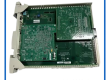
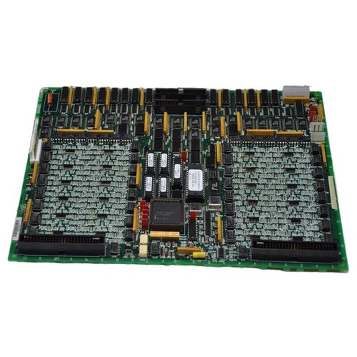
The GE DS215TCDAG1BZZ01A is a sophisticated digital input/output (I/O) board designed for the Mark V Speedtronic™ Turbine Control System. Operating within the <Q11> and <Q51> digital I/O cores, this board is a critical interface for processing discrete signals between the turbine and the central controller. It is specifically engineered to handle contact input signals from terminal boards and output relay/solenoid commands, ensuring millisecond-accurate timestamping for Sequence of Events (SOE) recording.
Key Product Specifications
- Part Number: DS215TCDAG1BZZ01A
- System Series: Mark V Speedtronic (DS200)
- Module Type: Digital I/O Board with Firmware
- Microprocessors: Features one onboard microprocessor for localized signal processing.
- Input Capacity: Processes contact input signals from DTBA and DTBB boards.
- Output Capacity: Manages relay/solenoid output signals to TCRA boards.
- Communication: Utilizes the IONET (JX1/JX2) for high-speed deterministic data transfer.
- Status Indicators: One bank of 10 diagnostic LEDs for health and fault monitoring.
- Dimensions: 160 mm x 160 mm x 120 mm
- Weight: 0.80 kg
- Country of Origin: USA
Connector Layout & Functions
The TCDA board utilizes specialized connectors to maintain system integrity across the Mark V architecture:
- JQ / JR Connectors: Conduit for contact input signals arriving from the DTBA and DTBB terminal boards.
- JO1 / JO2 Connectors: Transmit digital output commands to the TCRA relay boards in positions 4 and 5.
- JX1 / JX2 Connectors: Shielded twisted-pair connections for the IONET communication network.
- JP Connector: Receives regulated power from the TCPS (Power Supply) board to fuel the board’s internal logic.
Application Fields
The DS215TCDAG1BZZ01A is essential for the automation and protection of:
- Gas Turbine Control: Monitoring enclosure fire detectors, pressure switches, and start-up interlocks.
- Steam Turbine Management: Managing valve status indicators and trip circuit feedback.
- Combined Cycle Plants: Coordinating discrete logic across synchronized power generation units.
- Industrial Drives: Acting as a drive control interface in AC2000 and DC2000 series exciter systems.
Usage Instructions
- Installation: Mount the board in the designated card slot within the
<Q>core. Ensure the vertical pin plug connectors are fully seated to maintain continuous power and data flow. - Hardware Configuration: Use jumpers J4 through J6 to set the unique IONET ID for the board. Jumper J7 should be configured to enable or disable the stall timer based on your system requirements.
- Ribbon Cable Handling: When connecting the 50-pin ribbon cables, pull only on the plastic connector housing, not the cable itself, to avoid breaking the delicate internal strands.
- Diagnostics: Monitor the LED bank during startup. If the board fails to initialize, the diagnostic LEDs will display a specific fault pattern that corresponds to the Mark V alarm list for troubleshooting.
Q&A – Frequently Asked Questions
Q: Can I replace a DS200TCDA with a DS215TCDA? A: The “DS215” prefix typically indicates a board with integrated firmware (EPROMs). While functionally similar to the DS200 series, the DS215 variant is designed for systems that require the specific software revision included on the board’s memory chips.
Q: What happens if the JX1/JX2 IONET connection is lost? A: A loss of IONET communication will trigger a diagnostic alarm at the HMI. The board will typically enter a fail-safe state, but the lack of input data may cause the turbine controller to initiate a controlled shutdown or trip depending on the logic configuration.
Q: Are the jumpers J1 and J8 used in normal operation? A: No, J1 and J8 are reserved for factory testing and should remain in their default positions during standard field operation.
Product News: Sustaining Legacy Mark V Systems
The DS215TCDAG1BZZ01A remains a high-demand component as global power plants seek to extend the service life of their GE Mark V controllers. With the Speedtronic technology entering its late-lifecycle phase, the availability of boards with “ZZ01A” firmware packages is critical for maintaining compatibility with existing HMI databases. Recent engineering audits suggest that replacing aging TCDA boards proactively can significantly reduce the frequency of “Communication Failure” alarms, ensuring that the Sequence of Events (SOE) data remains reliable for regulatory reporting and post-trip analysis.