
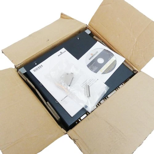
The Baumüller BUM60-08/16-54-B-001 is a modular AC drive power unit designed for industrial motor control applications. This configuration is supplied with the BUM60-VC-0A-0001 plug-in control unit, forming a drive assembly that combines the mains-side converter, motor-side inverter, and control electronics. The power section is rated for 8 A continuous output current and 16 A peak output current, with a nominal DC link voltage class of 540 V. It accepts three-phase 400–480 V AC input and provides variable-frequency three-phase motor output. The BUM 60 platform uses IGBT power electronics and an integrated ballast circuit to manage regenerated motor energy. The control unit provides the regulation and drive-control functions required by the application. This equipment is suitable for industrial machinery, machine tools, and motor-driven production systems. Before installation or replacement, verify the complete type code, controller revision, firmware and parameter set, motor feedback configuration, and compatibility with the existing Baumüller drive system.
📋 Product Specifications
| Parameter | Description |
|---|---|
| Brand | Baumüller |
| Power Unit Model | BUM60-08/16-54-B-001 |
| Control Unit Model | BUM60-VC-0A-0001 |
| Product Series | BUM 60 |
| Product Type | AC Servo Drive / Mono Power Unit |
| Configuration | Power section with plug-in control unit |
| Continuous Output Current | 8 A |
| Peak Output Current | 16 A |
| Nominal DC Link Voltage | 540 V DC |
| AC Input Voltage | 3 × 400–480 V AC ±10% |
| Input Frequency | 50/60 Hz |
| Motor Output Voltage | 0–390 V AC, three-phase (supplier-listed configuration) |
| Output Frequency Range | Up to 300 Hz (supplier-listed configuration) |
| Switching Technology | IGBT |
| Braking Circuit | Internal ballast transistor and ballast resistor |
| Control Unit | BUM60-VC-0A-0001 |
| Control Function | Motor regulation and drive control |
| Cooling | Verify exact cooling arrangement against the unit documentation |
| Power Consumption | Approx. 130 W reported by supplier; verify operating conditions |
| Dimensions | Approx. 315 × 108 × 270 mm (H × W × D), supplier-listed |
| Weight | Approx. 7–10 kg, depending on included components and measurement source |
| Place of Manufacture | Not confirmed |
| Country of Origin | Germany reported by supplier; verify nameplate |
| Product Status | Legacy industrial drive |
| Discontinued | Reported discontinued; confirm with manufacturer |
| Application | Industrial AC motor and servo drive control |
⚙️ Installation and Operation
- Installation: Isolate the three-phase power supply and verify DC link discharge before handling the drive. Check the mounting arrangement, power terminals, protective grounding, motor connections, and control-unit seating. Confirm that the BUM60-VC-0A-0001 is installed in the correct control slot.
- Power-On: Verify the input voltage, phase connections, control wiring, motor connections, and braking circuit. Apply power according to the Baumüller commissioning procedure and check the controller status indicators.
- Normal Operation: Monitor motor current, speed, load, temperature, and drive fault indications. Confirm that the motor responds correctly to the configured speed and torque commands.
- Parameter Configuration: Use the appropriate Baumüller commissioning documentation and compatible configuration tools. Verify motor data, feedback settings, current limits, control parameters, and application-specific settings. Back up the existing parameter set before making changes.
- Power-Off: Stop the motor using the machine’s approved shutdown sequence. Disable the drive, isolate the mains supply, and follow the OEM DC link discharge procedure before servicing.
🔧 Maintenance and Troubleshooting
- Drive does not start: Check the three-phase supply, control-unit seating, control voltage, fuses, and diagnostic indicators.
- Overcurrent fault: Inspect motor wiring, motor insulation, mechanical loading, and configured current limits.
- DC link fault: Check the incoming supply, DC link connections, and associated diagnostic messages.
- Braking circuit fault: Inspect the ballast circuit, braking resistor, wiring, and thermal condition.
- Motor speed instability: Verify motor feedback, control parameters, motor data, and mechanical load.
- Overtemperature alarm: Inspect cabinet ventilation, cooling components, ambient temperature, and mounting clearance.
- Control-unit communication fault: Check the BUM60-VC-0A-0001, connectors, firmware identification, and system configuration.
🛡️ Safety Precautions
- Installation and commissioning must be performed by qualified industrial electrical personnel.
- The drive contains hazardous AC and DC link voltages. Isolate the supply and verify discharge before servicing.
- Do not remove or insert the control unit while the drive is energized.
- Never disconnect motor cables while the inverter is operating.
- Use only braking components that meet the manufacturer’s electrical and thermal specifications.
- Maintain suitable cabinet ventilation and protective grounding.
- Verify motor compatibility, controller configuration, and firmware before commissioning.
- Test the machine’s emergency-stop and independent safety functions before returning equipment to production.
🔗 Related Baumüller Models
The following are related Baumüller BUM and BUS drive-system models. They are reference products, not guaranteed direct replacements for the BUM60-08/16-54-B-001 configuration.
- Baumüller BUM60-06/12-54-B-001
- Baumüller BUM60-08/16-54-B-000
- Baumüller BUM60-12/24-54-B-001
- Baumüller BUM60-30/60-31-B-000
- Baumüller BUM60-VC-0A-0001
- Baumüller BUM60-VC-0A-0002
- Baumüller BUM61-VC-0A-1035
- Baumüller BUM61-30/45-54-B-0
- Baumüller BUS60-08/16-54-0-001
- Baumüller BUS60-12/24-54-0-001
- Baumüller BUS621-10/15-54-O-001
- Baumüller BUS623-56-54-B-005
- Baumüller BUM617-12/18-31-R-0001
- Baumüller BUM60-12/24-54-B-000
- Baumüller BUM60-30/60-31-B-002


