
Product Introduction
The KUKA 00-110-185 KCP2 Control Panel is a handheld teach pendant designed for operator control, robot programming, manual jogging, and status monitoring in KUKA KR C2 robot control systems. It serves as the primary human-machine interface between the operator and the robot controller, combining a color LCD display, keyboard, function keys, mode selector, emergency-stop button, enabling switches, and a Space Mouse for manual robot movement. The KCP2 communicates with the controller through the control panel’s internal CAN bus and safety-related ESC bus architecture. With a nominal 24 V DC supply, this pendant is an important service and replacement component for existing KUKA KR C2 installations. Before purchasing or installing a replacement, verify the complete part number, cable assembly, controller generation, and hardware revision to ensure compatibility with the existing robot system.
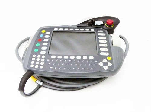
Technical Specifications
- Brand: KUKA
- Model: 00-110-185
- Alternative Model Identification: KCP2 / KCP2 Standard
- Product Series: KUKA Control Panel (KCP)
- Compatible Robot Controller Family: KR C2
- Product Name: KCP2 Robot Teach Pendant Control Panel
- Product Type: Handheld Robot Operator Panel / Teach Pendant
- Primary Application: Industrial robot operation and programming
- Display Type: Color LCD
- Display Size: Approximately 8 inches, according to product references
- Display Resolution: 640 × 480 pixels (VGA)
- Display Color Capability: 256 colors, according to KUKA KCP2 documentation
- User Input: Integrated keyboard and function keys
- Manual Movement Control: Space Mouse and robot jogging keys
- Operating Mode Selection: Key-operated mode selector
- Safety Controls: Emergency-stop button and three-stage enabling switches
- Internal Communication Architecture: CAN bus and ESC safety bus
- Rated Supply Voltage: 24 V DC
- Rated Current: 0.5 A
- Cable Configuration: Standard KR C2 catalog configuration lists a 10 m cable
- Mounting / Installation: Handheld operator station connected to the robot controller
- Dimensions: Approximately 400 × 400 × 130 mm reported by one distributor; verify the actual enclosure drawing
- Weight: Approximately 2.7–3.6 kg depending on the referenced configuration and measurement source
- Power Supply: Provided by the compatible robot controller connection
- Place of Manufacture: Not reliably published
- Country of Origin: Verify the original product label and packaging
- Product Status: Legacy KR C2 spare part; current OEM availability requires confirmation
- Condition: New surplus, unused, or refurbished depending on the supplied unit
Key Technical Features
- Integrated Robot Operator Interface: Combines robot programming, manual operation, system monitoring, and operator controls in one handheld device.
- Color LCD Display: Displays robot status, programming information, operating modes, coordinates, and diagnostic messages.
- Space Mouse Control: Provides an alternative method for manually moving the robot during teaching and setup operations.
- Mode Selector: Allows authorized operators to select supported robot operating modes using the key-operated selector.
- Emergency-Stop Function: Provides an emergency-stop control integrated into the KUKA robot control panel safety architecture.
- Three-Stage Enabling Switches: Supports the enabling function required for authorized manual robot operation.
- CAN Bus Communication: Supports communication for the display, keyboard, function keys, and Space Mouse functions.
- ESC Safety Bus: Connects safety-related operator controls, including the emergency-stop circuit, enabling switches, and operating-mode selection.
- 24 V DC Operation: Uses the compatible KUKA controller connection for its nominal power supply.
- KR C2 System Integration: Designed for the KUKA KR C2 robot controller generation and its corresponding control architecture.
Typical Application Scenarios
- Automotive manufacturing robot cells
- Industrial welding and handling robots
- Material loading and unloading systems
- Robot teaching and programming stations
- Automated assembly lines
- Machine tending applications
- Robot maintenance and troubleshooting
- KUKA KR C2 legacy system restoration
- Industrial robot spare-parts replacement
Operating Procedures
1. Installation and Connection
- Confirm the pendant identification label shows 00-110-185.
- Verify that the robot controller is a compatible KR C2 configuration.
- Inspect the pendant housing, LCD, keyboard, Space Mouse, emergency-stop button, and enabling switches.
- Inspect the cable and connector for cuts, crushing, bent contacts, or damaged locking mechanisms.
- Confirm that the cable assembly matches the controller connection.
- Follow the KUKA installation documentation for connecting the KCP2.
- Do not force the connector into the controller interface.
- Verify that the emergency-stop and enabling circuits are correctly recognized by the controller.
- Keep the cable away from sharp edges, hot surfaces, and robot travel paths.
2. Startup and Power-On
- Confirm that the robot cell is clear of personnel and obstacles.
- Verify that the emergency-stop circuit and protective devices are in the required condition.
- Switch on the robot controller according to the machine operating procedure.
- Allow the KCP2 to complete its startup sequence.
- Check the display for system status, initialization messages, and active faults.
- Confirm that the mode selector operates correctly.
- Verify that the enabling switches and emergency-stop function are recognized.
- Do not enable robot motion until the complete safety system has passed the required checks.
3. Normal Operation
- Use the display to monitor robot status, coordinates, programs, and diagnostic information.
- Select the authorized operating mode using the mode selector.
- Use the jogging keys or Space Mouse for manual robot movement.
- Follow the prescribed enabling-switch procedure during manual operation.
- Use the keyboard and function keys to access programming and operating functions.
- Monitor the robot controller for active alarms and system warnings.
- Keep the pendant cable clear of moving robot axes and surrounding equipment.
- Only trained personnel should operate the robot in manual or automatic modes.
4. Parameter Configuration and Program Modification
- Back up the robot program and machine configuration before making changes.
- Use the KUKA-supported programming environment for the installed KR C2 system.
- Verify the active operating mode and authorization level.
- Review tool data, base data, motion parameters, and program settings before modification.
- Make changes only under the machine manufacturer’s approved procedure.
- Test modified robot programs at an appropriate reduced speed and in a controlled operating mode.
- Confirm the correct operation of all safety devices before returning the cell to production.
5. Shutdown
- Stop the robot using the approved operating procedure.
- Move the robot to the designated safe position where required.
- Exit active programming or maintenance operations.
- Follow the controller shutdown sequence.
- Isolate the system before disconnecting the pendant for maintenance.
- Store the pendant in its designated holder to prevent impact or cable damage.
Daily Maintenance
- Inspect the LCD for cracks, dead pixels, and abnormal display behavior.
- Clean the screen with a soft, lint-free cloth.
- Check the keyboard and function keys for sticking or intermittent response.
- Inspect the Space Mouse for smooth movement and normal operation.
- Test the enabling switches according to the plant’s approved inspection procedure.
- Check the emergency-stop button and verify its function through the prescribed safety test.
- Inspect the cable for cuts, kinks, abrasion, and damaged strain relief.
- Check the connector contacts and locking mechanism.
- Keep the pendant away from oil, metal chips, coolant, and excessive moisture.
- Record recurring faults and arrange repair if any safety-related control behaves abnormally.
Troubleshooting Guide
Problem: KCP2 display remains blank
- Check whether the robot controller is powered on.
- Verify the pendant cable and connector.
- Confirm the nominal 24 V DC supply is available at the appropriate interface.
- Check the controller’s diagnostic messages.
- Investigate possible display or internal hardware faults.
Problem: Keyboard or function keys do not respond
- Check for damaged or stuck keys.
- Inspect the pendant cable and connector.
- Verify communication between the KCP2 and the controller.
- Check for internal keypad or CAN bus faults.
Problem: Space Mouse does not move the robot
- Confirm the selected operating mode.
- Verify that the enabling switch is being operated correctly.
- Check whether the controller reports active safety or motion-permission faults.
- Inspect the Space Mouse and pendant communication functions.
- Confirm that the selected jogging frame and axis configuration are correct.
Problem: Emergency-stop circuit remains active
- Check the emergency-stop button and its mechanical condition.
- Inspect the pendant cable and safety-related connection.
- Check other emergency-stop devices in the robot cell.
- Review the controller safety diagnostics.
- Do not bypass the emergency-stop circuit to restore operation.
Problem: Enabling switch does not work
- Check the three-stage switch for mechanical damage.
- Verify that the correct enabling position is being used.
- Inspect the cable and connector.
- Review the controller’s safety-related diagnostic messages.
- Replace or repair the pendant if the enabling function cannot be verified.
Problem: Controller does not recognize the KCP2
- Confirm the correct KCP2 model and controller generation.
- Inspect the connection and connector locking.
- Check the controller interface and communication status.
- Verify that the pendant is configured for the installed KR C2 system.
- Consult the KUKA service documentation before replacing controller interface components.
Frequently Asked Questions
Q1: What is the KUKA 00-110-185?
It is a KCP2 handheld teach pendant used for programming, manual jogging, monitoring, and operating compatible KUKA robot systems.
Q2: Which robot controller is it designed for?
The 00-110-185 KCP2 Standard is associated with the KUKA KR C2 controller family.
Q3: What is the rated supply voltage?
Distributor specifications identify a nominal supply of 24 V DC and a rated current of 0.5 A.
Q4: Does the KCP2 have an emergency-stop button?
Yes. It includes an emergency-stop control integrated into the robot controller’s safety architecture.
Q5: Does it support manual robot movement?
Yes. The KCP2 provides jogging controls and a Space Mouse for manual robot movement during authorized teaching and setup operations.
Q6: Is the KCP2 compatible with KRC4 or KRC5 controllers?
Do not assume compatibility. The 00-110-185 is a KR C2-generation KCP2. KRC4 and KRC5 systems use different operator-panel generations and connection architectures.
Q7: What cable length does the standard version use?
The KUKA KR C2 spare-parts catalog identifies the standard 00-110-185 configuration with a 10 m cable. Confirm the actual cable supplied with the individual unit.
Q8: What should be checked before purchasing a replacement?
Verify the complete part number, controller generation, cable condition, connector, display, keyboard, Space Mouse, emergency-stop button, and enabling-switch operation.
Safety Precautions
- ⚠️ Only trained and authorized personnel should operate the KUKA robot system.
- ⚠️ Never bypass or modify the emergency-stop circuit.
- ⚠️ Never bypass the enabling-switch function.
- ⚠️ Verify the complete robot cell safety system before enabling motion.
- ⚠️ Keep personnel outside the robot’s hazardous movement area during operation.
- ⚠️ Do not use a damaged pendant, cable, or connector.
- ⚠️ Disconnect power according to the approved maintenance procedure before servicing the pendant.
- ⚠️ Do not connect a KR C2 KCP2 to another controller generation without explicit compatibility confirmation.
- ⚠️ Test all safety-related pendant functions after replacement or repair.
- ⚠️ Follow the applicable KUKA operating instructions and plant safety procedures.
Related KUKA Models and Components
The following products belong to related KUKA robot controller, operator-panel, and spare-parts families. They are useful for maintenance planning and system identification, but they are not all direct substitutes for the 00-110-185.
- 00-130-647 – KUKA KCP2 Standard Operator Panel, later KR C2 configuration
- 00-107-264 – KUKA KCP2 VW Operator Panel
- 00-105-201 – KUKA KCP1.5 Operator Panel
- 00-108-849 – KUKA KCP2 Connection Cable, verify cable execution
- 00-121-154 – KUKA KC2 Controller Component
- 00-111-846 – KUKA KRC2 Power Module
- 00-115-115 – KUKA KPS-600/20 Power Supply Module
- 00-117-344 – KUKA KSD1-48 Servo Module
- 00-122-284 – KUKA KSD1-08 Servo Module
- 00-122-285 – KUKA KSD1-16 Servo Module
- 00-194-763 – KUKA KRC4 Cabinet Interface Board (CIB)
- 00-198-260 – KUKA KPP600-20 Power Pack
- 00-198-263 – KUKA KPP600-20 Power Pack
- 00-198-266 – KUKA KSP 600-3X20 Servo Pack
- KUKA SmartPAD – KRC4/KRC5-generation operator interface family
Compatibility Note: The KCP2 00-110-185 is intended for the KR C2 generation. KCP1.5, later KCP2 variants, SmartPAD units, controller power modules, and servo modules have different functions or hardware interfaces. Confirm the exact controller generation and connection architecture before ordering a replacement.


