
Product Introduction
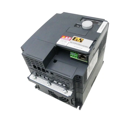
The B&R 8I66T400400.0P-000 is an ACOPOSinverter P66 industrial frequency inverter designed for three-phase motor control in automated machinery and industrial drive systems. It belongs to B&R’s P66 inverter platform and is rated for 4 kW motor applications with a three-phase input supply range of 380 to 500 V AC. This version is equipped with a POWERLINK communication card for integration into compatible B&R automation networks. The inverter incorporates an EMC filter and brake chopper, with a shield plate included in the standard delivery configuration. It is intended for applications requiring controlled motor speed, acceleration, deceleration, and braking within a coordinated machine-control system. The product’s base-device reference is 8I66T400400.00-000, while the complete 8I66T400400.0P-000 order code identifies the POWERLINK-equipped P66 version. When selecting a replacement, verify the communication interface, hardware revision, motor ratings, wiring arrangement, and Automation Studio hardware configuration.
Technical Parameters
- Brand: B&R (Bernecker + Rainer)
- Model: 8I66T400400.0P-000
- Base Device Number: 8I66T400400.00-000
- Product Series: ACOPOSinverter P66
- Product Family: B&R ACOPOSinverter P66 / P64new
- Product Name: ACOPOSinverter Frequency Drive
- Product Type: Industrial variable-frequency inverter
- Rated Motor Power: 4 kW
- Input Supply: Three-phase 380–500 V AC
- Communication Interface: POWERLINK
- EMC Filter: Integrated
- Brake Chopper: Integrated
- Shield Plate: Included in standard delivery configuration
- Degree of Protection: IP20
- Installation Position: Vertical mounting, ±10°
- Dimensions: 140 mm wide × 228 mm high × 158 mm deep
- Height Without Shield Plate: 184 mm
- Weight: Approximately 2.2 kg
- Operating Temperature: -10 to 50°C without derating; 50 to 60°C with derating
- Storage Temperature: -25 to 70°C
- Relative Humidity: 5–95%, non-condensing
- Maximum Installation Altitude: 1,000 m without derating; 1,000–3,000 m with derating
- Pollution Degree: 2, non-conductive pollution
- Mounting: Electrical control cabinet
- Control Platform: B&R ACOPOSinverter P66
- Engineering Environment: B&R Automation Studio, with compatible hardware upgrade and configuration files
- Place of Manufacture: B&R manufacturing network; exact factory for this unit is unverified
- Country of Origin: Verify the product nameplate
- Product Status: Confirm current availability and lifecycle status with B&R
- Condition: Confirm the actual item’s condition and included accessories with the seller
Key Technical Features
- 4 kW drive rating: Designed for compatible three-phase industrial motor applications up to the specified power class.
- POWERLINK communication: Provides integration with compatible B&R automation controllers and networks.
- Integrated EMC filter: Helps control electromagnetic interference within the limits of the applicable installation requirements.
- Integrated brake chopper: Supports connection of an appropriate external braking resistor for controlled deceleration.
- P66 platform compatibility: Belongs to the ACOPOSinverter P66 family and shares the documented base-device platform with P64new configurations.
- Compact cabinet installation: A 140 mm-wide enclosure supports installation in industrial control cabinets.
- Industrial environmental rating: IP20 protection is intended for installation inside a suitable electrical enclosure.
- Configurable motor control: Supports drive configuration through the applicable B&R engineering environment.
- Shield plate included: Supports the intended cable-shielding and EMC installation arrangement.
Typical Applications
- Industrial conveyor systems
- Packaging and processing machinery
- Production-line motor control
- Material-handling equipment
- Pump and fan applications
- Industrial machine-tool auxiliaries
- Automated assembly equipment
- B&R POWERLINK-based machine architectures
Installation Procedure
- Verify the complete model number, including the 0P-000 suffix, to confirm the POWERLINK version.
- Check the motor nameplate and confirm that its power and electrical requirements are suitable for the inverter.
- Confirm that the incoming three-phase supply is within the specified 380–500 V AC range.
- Select a suitable electrical cabinet with adequate ventilation and mounting clearance.
- Install the inverter in the specified vertical orientation.
- Secure the unit using the mounting points and hardware specified in the B&R mechanical documentation.
- Connect the incoming supply, motor output, protective earth, and braking-resistor wiring according to the P66 wiring diagram.
- Install the supplied shield plate and terminate cable shields using the specified EMC arrangement.
- Connect the POWERLINK communication cable to the appropriate network interface.
- Verify that the connected controller supports the required P66 hardware configuration.
- Inspect all terminal connections, protective grounding, and cable routing.
- Confirm that the installation complies with cabinet temperature, humidity, and pollution requirements before energizing.
Startup and Power-On
⚠️ The inverter operates from a high-voltage three-phase supply. Installation and commissioning must be performed by qualified electrical and automation personnel.
- Check the incoming supply voltage and protective-device ratings.
- Verify the motor power wiring and protective earth connection.
- Confirm that the braking resistor, if required, is correctly selected and connected.
- Check the POWERLINK network cable and controller configuration.
- Confirm that the inverter is installed vertically with sufficient cooling clearance.
- Apply power according to the B&R commissioning procedure.
- Check the inverter status and diagnostic indications.
- Establish communication with the B&R controller.
- Verify the detected hardware configuration in Automation Studio.
- Enter the motor identification and operating parameters.
- Test motor direction and feedback behavior at a controlled speed.
- Increase the operating load gradually while monitoring current, temperature, and drive diagnostics.
Normal Operation
During normal operation, the ACOPOSinverter P66 controls the connected motor according to commands received through the configured automation system. The POWERLINK interface enables communication with compatible B&R controllers, allowing drive commands and status information to be exchanged within the machine-control network.
Operators should monitor drive status, motor current, operating temperature, communication health, and braking behavior. The inverter must operate within its specified electrical and environmental limits. The integrated brake chopper does not eliminate the need to select and connect an appropriate external braking resistor when the application requires one.
Parameter Configuration and Modification
- Use the B&R ACOPOSinverter P66 documentation applicable to the installed hardware revision.
- Confirm the complete inverter order number and POWERLINK interface configuration.
- Use a compatible Automation Studio version and hardware upgrade package.
- Configure the motor’s rated voltage, current, power, frequency, and speed according to its nameplate.
- Set acceleration and deceleration ramps according to the mechanical load.
- Configure the required operating mode and speed limits.
- Verify POWERLINK network settings and controller-side hardware identification.
- Configure braking parameters according to the connected braking resistor and application requirements.
- Check current limits and motor protection settings.
- Back up the existing configuration before modifying parameters.
- Do not load a configuration from a P64 or another P66 variant without checking hardware compatibility.
- Perform a controlled functional test after parameter changes.
Shutdown Procedure
- Stop the connected machine using its normal operating sequence.
- Reduce the motor speed and command the drive to a controlled stop.
- Confirm that the motor and driven equipment are in a safe condition.
- Disable the inverter through the machine controller.
- Isolate the incoming electrical supply before maintenance.
- Apply lockout/tagout procedures.
- Wait for the DC-link capacitors to discharge according to the manufacturer’s instructions.
- Verify the absence of hazardous voltage using an appropriately rated measuring instrument.
- Disconnect power, motor, or communication cables only after confirming that the equipment is safe.
Daily Maintenance
- Inspect the inverter enclosure for dust, oil, moisture, or other contamination.
- Check cabinet ventilation and cooling airflow.
- Inspect the power terminals for discoloration, looseness, or overheating.
- Check motor cables and protective earth connections.
- Inspect the POWERLINK cable and connector condition.
- Verify that the shield plate and cable-shield terminations remain secure.
- Review inverter diagnostics and stored fault information.
- Check the braking resistor and associated wiring where fitted.
- Monitor operating temperature and abnormal noise from the connected motor.
- Keep the installation within the specified temperature and humidity limits.
- Follow B&R maintenance instructions for periodic inspection and replacement of wear components.
Troubleshooting
1. Inverter does not power up
- Check the three-phase input supply.
- Inspect upstream fuses and circuit protection.
- Verify power-terminal connections.
- Check the inverter status and diagnostic indicators.
- Confirm that the installation meets the specified supply requirements.
2. POWERLINK communication failure
- Inspect the POWERLINK cable and connectors.
- Verify the controller configuration and network topology.
- Check that the correct P66 hardware configuration is selected in Automation Studio.
- Confirm compatibility of the hardware upgrade package and engineering software.
- Review controller and inverter diagnostic messages.
3. Motor does not start
- Check the drive-enable command and machine interlocks.
- Verify motor wiring and parameter configuration.
- Check for active inverter faults.
- Confirm that the motor is compatible with the drive’s power rating.
- Inspect braking-system wiring if the motor cannot release or move.
4. Overcurrent or overload alarm
- Check for mechanical blockage or excessive load.
- Verify motor nameplate data and drive settings.
- Review acceleration and deceleration times.
- Inspect motor cable insulation and connections.
- Confirm that the connected motor is suitable for the application.
5. DC-link or braking fault
- Check the braking-resistor connection and specification.
- Inspect the braking circuit for damaged wiring.
- Verify the deceleration profile and regenerative energy conditions.
- Check the drive diagnostic information before replacing components.
6. Inverter overtemperature
- Check cabinet temperature and airflow.
- Inspect ventilation openings and surrounding equipment.
- Verify that the inverter is mounted in the specified orientation.
- Check the load against the inverter’s rated power.
- Apply the required derating if operating above 50°C.
Frequently Asked Questions
Q1: What is the B&R 8I66T400400.0P-000?
It is a 4 kW ACOPOSinverter P66 industrial frequency drive equipped with a POWERLINK communication card.
Q2: What is its rated input voltage?
The manufacturer’s product data specifies a three-phase input range of 380–500 V AC.
Q3: What is the difference between 8I66T400400.00-000 and 8I66T400400.0P-000?
The .00-000 number identifies the base-device material number. The .0P-000 order number identifies the P66 inverter configuration with a POWERLINK communication card.
Q4: Does the inverter include an EMC filter?
Yes. The documented 4 kW base-device configuration includes an integrated EMC filter.
Q5: Does it have a built-in brake chopper?
Yes. The base-device specification identifies an integrated brake chopper. An external braking resistor may still be required, depending on the application.
Q6: Can it be used with an ACOPOSinverter P64?
The B&R product documentation identifies the base-device platform as suitable for ACOPOSinverter P66 and P64new. However, the complete communication-card configuration differs. Confirm the exact P64/P66 order code and controller compatibility before substitution.
Q7: What are the physical dimensions and weight?
The documented dimensions are 140 × 228 × 158 mm, with a weight of approximately 2.2 kg. The height without the shield plate is 184 mm.
Q8: Which software is required for configuration?
B&R Automation Studio with the compatible ACOPOSinverter P66 hardware upgrade and device description files. Confirm the software and hardware revision before commissioning.
Safety Precautions
⚠️ Electrical Safety: Disconnect and isolate the incoming three-phase supply before installation or maintenance.
⚠️ Stored Energy: The DC link may retain hazardous voltage after power-off. Observe the specified discharge time and verify the voltage before servicing.
⚠️ Protective Grounding: Connect protective earth according to the B&R wiring instructions.
⚠️ Braking Resistor: Use only a braking resistor with the correct electrical rating and installation arrangement.
⚠️ EMC Installation: Install the shield plate and cable shields according to the manufacturer’s EMC recommendations.
⚠️ Environmental Protection: IP20 equipment must be installed inside a suitable cabinet protected from direct contact, water, and conductive contamination.
⚠️ Configuration Compatibility: Confirm the POWERLINK interface and hardware revision before replacing an existing inverter.
Related B&R Models and Configurations
The following are verified related ACOPOSinverter P66/P64new references and communication variants. They are useful for comparison, but are not all direct replacements for the 4 kW POWERLINK version.
- 8I66T400150.00-000 – P66/P64new base device, 1.5 kW
- 8I66T400220.00-000 – P66/P64new base device, 2.2 kW
- 8I66T400300.00-000 – P66/P64new base device, 3 kW
- 8I66T400400.00-000 – P66/P64new base device, 4 kW
- 8I66T400400.0P-000 – P66, 4 kW, POWERLINK
- 8I66T400400.0X-000 – P66, 4 kW, X2X Link
- 8I66T400400.0C-000 – P66, 4 kW, integrated CANopen
- 8I64T400400.0X-000 – P64new, 4 kW, X2X Link
Replacement Note: These references cover the documented power classes and communication configurations. The communication interface, input supply, power rating, hardware revision, and controller configuration must match the machine requirements. Do not substitute an X2X Link or CANopen version for a POWERLINK unit without checking the control-system architecture.


