
Product Description
The KUKA ECMAP1D3404BE531 is a KPP 600-20-1×40 power and servo drive module designed for compatible KUKA KR C4 robot controller systems. It combines a three-phase AC power supply stage with a single-axis servo amplifier, providing DC intermediate-circuit power and controlled motor output for industrial robotic motion. The module is identified by KUKA ID number 13342284 and product number 03571401, with hardware version 2A. It is intended for integration into the corresponding KUKA controller cabinet and must be matched to the robot’s drive configuration, motor requirements, and system wiring before installation.
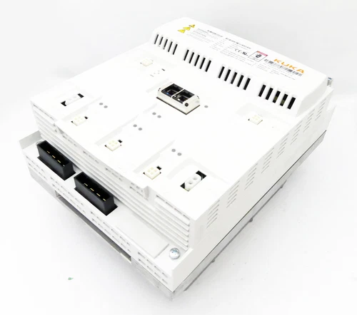
Product Datasheet
- Brand: KUKA
- Product Series: KPP 600
- Model: ECMAP1D3404BE531
- KUKA ID Number: 13342284
- Product Number: 03571401
- Hardware Version: 2A
- KPP Configuration: KPP 600-20-1×40
- Product Type: Power supply and single-axis servo drive module
- Controller Application: Compatible KUKA KR C4 configurations
- Input Voltage: 3/PE AC 400/480 V
- Input Current: 20 A
- Input Frequency: 50/60 Hz
- Rated Power: 14/17 kW
- DC Intermediate Circuit Output: 2/PE DC 565/675 V, 25 A
- Motor Output: 3/PE AC, 0–400/480 V
- Motor Output Frequency: 0–500 Hz
- Motor Output Current: 17 A
- Motor Output Power: 12/14 kW
- Axis Amplifier Configuration: 1 × 40 A peak
- Protection Rating: IP20, verify against the applicable KUKA documentation
- Weight: Approximately 9 kg, seller-listed specification
- Condition: Subject to seller confirmation
- Country of Origin: Not verified
Operating Guidelines and Usage
- Verify the complete part number, KUKA ID number, product number, and hardware version against the existing controller configuration.
- Confirm that the module is intended for the specific KR C4 cabinet and robot model.
- Check the robot motor ratings, axis assignment, feedback connections, and drive configuration before installation.
- Inspect the module, power terminals, DC bus connections, and motor output connectors for damage.
- Confirm that the incoming three-phase supply matches the module’s specified voltage and current requirements.
- Verify protective earth, cabinet grounding, cable shielding, and required upstream protection.
- Check the DC bus and braking resistor arrangement against the controller documentation.
- Complete the KUKA controller configuration and diagnostic checks before enabling robot motion.
Power-On and Power-Off Sequence
Power-On
- Inspect the module and cabinet wiring with the system isolated.
- Confirm that the three-phase input supply and protective earth connections are correct.
- Verify the DC bus, motor cables, feedback connections, and braking circuit.
- Ensure that all cabinet covers and protective devices are correctly installed.
- Apply power according to the KUKA KR C4 controller startup procedure.
- Check controller diagnostics and confirm that the drive module is recognized.
- Enable the servo system only after all safety and drive checks have passed.
- Perform a controlled low-speed test before returning the robot to automatic operation.
Power-Off
- Stop robot motion and place the robot in the approved safe state.
- Disable the servo drives through the controller.
- Shut down the controller using the prescribed procedure.
- Isolate the incoming power supply and apply lockout/tagout.
- Allow the DC bus to discharge for the period specified in the KUKA manual.
- Verify the absence of hazardous voltage with a properly rated instrument before servicing.
Normal Operating Procedure
- Monitor controller and drive diagnostics during robot operation.
- Check for drive faults, DC bus warnings, overcurrent conditions, and thermal alarms.
- Confirm that the motor and feedback cables remain securely connected.
- Maintain cabinet ventilation and keep the module’s cooling paths clear.
- Monitor the braking resistor and associated wiring during applications involving frequent deceleration.
- Avoid exceeding the module’s rated current, power, and motor frequency limits.
- Record recurring faults and operating conditions to support maintenance diagnosis.
Parameter Settings and Modification
The ECMAP1D3404BE531 is a power and servo drive module within the KUKA controller architecture. Motor and axis behavior is configured through the compatible KUKA robot controller and its approved commissioning software.
Before changing settings:
- Verify the robot model, axis assignment, and motor identification data.
- Confirm that the configured motor current and speed limits match the installed motor.
- Check feedback-device type and connection compatibility.
- Verify braking resistor configuration and DC bus requirements.
- Confirm controller software and drive hardware compatibility.
- Back up the robot controller configuration before making changes.
- Do not modify safety-related parameters or bypass drive protection functions without an approved engineering procedure.
Maintenance and Troubleshooting
Preventive Maintenance
- Inspect power and motor terminals for looseness, discoloration, or overheating.
- Check cabinet ventilation and cooling components.
- Inspect grounding and cable shielding connections.
- Review controller fault history for repeated drive or DC bus alarms.
- Check braking resistor wiring and mounting condition.
- Inspect connectors and harnesses for mechanical damage.
- Follow KUKA maintenance intervals and inspection procedures.
Troubleshooting
- Module not recognized: Verify hardware identification, cabinet connections, and controller configuration.
- DC bus fault: Check incoming supply voltage, DC bus connections, and braking circuit.
- Overcurrent alarm: Inspect motor wiring, motor condition, mechanical load, and configured current limits.
- Motor does not move: Check servo enable status, axis assignment, feedback signals, and controller interlocks.
- Overtemperature alarm: Inspect cabinet cooling, ambient temperature, and drive loading.
- Intermittent drive faults: Check connector integrity, grounding, cable shielding, and supply stability.
Internal repair and electrical testing should be performed only by qualified personnel familiar with KUKA servo systems.
Safety Precautions
- The module uses hazardous three-phase AC and high-voltage DC intermediate-circuit power.
- Isolate all power sources and apply lockout/tagout before installation or maintenance.
- Never assume the DC bus is discharged; verify voltage independently before touching terminals.
- Use correctly rated cables, protective devices, and grounding connections.
- Do not disconnect motor or DC bus wiring while the drive system is energized.
- Do not bypass controller interlocks, braking protection, or robot safety functions.
- Verify hardware and software compatibility before replacing a module.
- Follow the applicable KUKA KR C4 installation, commissioning, and safety documentation.
Recommended Related KUKA Models
The following KUKA components and drive models are related to KR C4 power and servo systems. They are not all direct replacements; verify electrical ratings, axis configuration, hardware revision, and controller compatibility before ordering.
- ECMAP0D3004BE531 – KUKA servo drive / power module
- ECMAP1D3704BE531 – KUKA servo drive / power module
- KPP 600-20-1×40 – KUKA power pack configuration
- KPP 600 series – KUKA power supply modules
- KSP 600 series – KUKA servo drive modules
- KSP 600-3×20 – KUKA multi-axis servo drive
- KSP 600-3×40 – KUKA multi-axis servo drive
- KPP 600-20 – KUKA power supply family
- KUKA KR C4 – Robot controller platform
- KUKA KR C4 compact – Robot controller platform
- KUKA KR C4 extended – Robot controller platform
- KUKA KSP drive modules – Servo drive components for KR C4 systems
- KUKA KPP power modules – Controller power supply components
- KUKA KSD1 series – Servo drive modules used in other KUKA controller generations
- KUKA 00-198-260 – Associated KPP 600-20-1×40 module identification


