
The B&R Automation 8B0P0220HW00.000-E is a passive power supply module designed for the ACOPOSmulti modular servo drive system. It supplies the shared DC bus for connected inverter modules, providing power distribution for multi-axis motion-control applications in industrial machinery. The module supports three-phase 380–500 V AC input and has a rated supply current of 22 A, with a continuous DC bus supply power of approximately 8 kW and peak power of up to 24 kW under specified operating conditions. It features an integrated connection for an external braking resistor, overload protection, and short-circuit and ground-fault protection. Its wall-mounted design is suitable for ACOPOSmulti drive configurations used in packaging equipment, machine tools, material handling, and automated production lines. This is a passive supply module and does not provide regenerative energy feedback to the mains. Before installation or replacement, verify the complete material number and hardware revision, ACOPOSmulti system configuration, DC bus requirements, external braking resistor specifications, and mandatory terminal block accessories.
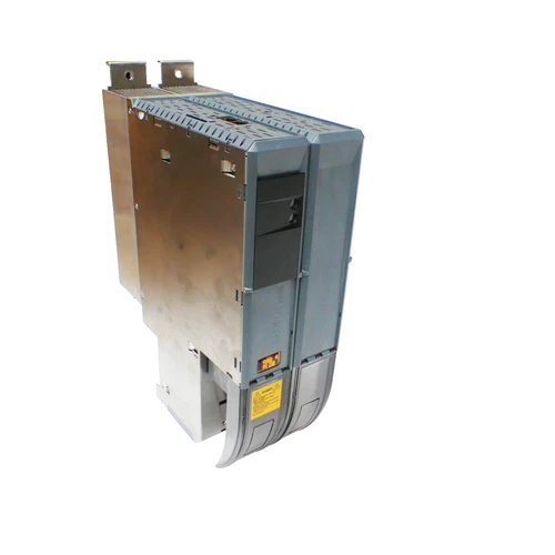
📋 Product Specifications
| Parameter | Description |
|---|---|
| Brand | B&R Automation |
| Model | 8B0P0220HW00.000-E |
| Product Series | ACOPOSmulti |
| Product Type | Passive Power Supply Module |
| Module Family | 8B0P |
| Rated Supply Current | 22 A |
| Mains Input Voltage | 3 × 380–500 V AC ±10% |
| Input Frequency | 50/60 Hz ±4% |
| Maximum Installed Load | 15.6 kVA |
| Continuous DC Bus Supply Power | Approx. 8 kW |
| Peak DC Bus Supply Power | Approx. 24 kW |
| Nominal DC Bus Voltage | 537–707 V DC |
| Power Conversion Type | Passive, non-regenerative |
| Regenerative Capability | No |
| Integrated Line Filter | No |
| Integrated Regeneration Choke | No |
| External Braking Resistor | Supported |
| Continuous Braking Power | 3 kW |
| Peak Braking Power | 40 kW, maximum 0.2 s |
| Minimum Braking Resistance | 12 Ω |
| Braking Protection | Overload, short-circuit, and ground-fault protection |
| Control Supply | 25 V DC ±1.6%, ACOPOSmulti backplane |
| Maximum Control Supply Consumption | 12 W |
| Mounting Type | Wall mounting |
| Protection Rating | IP20 |
| Permitted Mounting Positions | Vertical hanging or horizontal, face up |
| Operating Temperature | 5–40°C nominal; up to 55°C subject to derating |
| Relative Humidity | 5–85%, non-condensing |
| Dimensions | 317 × 106.5 × 263 mm (H × W × D) |
| Weight | Approx. 5.9 kg |
| Required Accessories | ACOPOSmulti terminal block set |
| Place of Manufacture | Not confirmed |
| Country of Origin | Austria reported by some listings; verify individual unit nameplate |
| Product Status | ACOPOSmulti product family; availability varies |
| Discontinued | Exact lifecycle status not confirmed |
⚙️ Installation and Operation
- Installation: Disconnect the three-phase supply and verify that the DC bus is discharged before installation. Mount the module in the specified wall-mounted position. Check the L1, L2, L3, PE connections, protective grounding, DC bus connections, and required terminal block accessories. Confirm that the mounting plate and connected inverter modules are compatible.
- Power-On: Verify the mains voltage, phase connections, protective earth, control supply, and external braking resistor wiring. Follow the ACOPOSmulti system startup sequence and observe the module and drive-system diagnostics.
- Normal Operation: Monitor DC bus voltage, connected inverter loads, braking activity, and system temperature. Ensure that the total connected drive power remains within the supply module’s permitted operating limits.
- Parameter and Configuration Changes: Configure the ACOPOSmulti drive system using compatible B&R engineering software. Check the connected inverter ratings, DC bus capacitance, braking resistor data, and system power calculations before changing the configuration.
- Power-Off: Stop all connected axes using the approved machine shutdown sequence. Disable the drive system, isolate the mains supply, and observe the OEM discharge waiting time. Verify DC bus voltage before removing the module or changing wiring.
🔧 Maintenance and Troubleshooting
- DC bus does not charge: Check the three-phase input, fuses, supply wiring, terminal connections, and system startup sequence.
- DC bus voltage abnormal: Verify input voltage, connected drive configuration, DC bus wiring, and supply loading.
- Braking resistor fault: Inspect resistor wiring, resistance, thermal condition, and the braking circuit protection.
- Overtemperature alarm: Check cabinet ventilation, module mounting orientation, ambient temperature, and cooling conditions.
- Supply overload: Review the total connected inverter power, simultaneous axis demand, and system derating requirements.
- Intermittent operation: Inspect power terminals, grounding, DC bus connections, and signs of overheating or loose connections.
- System configuration error: Verify the material number, hardware revision, connected modules, and ACOPOSmulti system configuration.
🛡️ Safety Precautions
- Installation and maintenance must be performed by qualified industrial electrical personnel.
- Three-phase AC input and the high-voltage DC bus present serious electrical hazards.
- Isolate the power supply and verify DC bus discharge before servicing.
- Never disconnect DC bus or braking resistor connections while energized.
- Use an external braking resistor that meets the specified resistance and power requirements.
- Consider the possibility of continuous braking resistor power during a component fault; provide suitable thermal protection and installation safeguards.
- Maintain the specified mounting orientation, cabinet ventilation, and environmental conditions.
- Do not assume that passive and active ACOPOSmulti supply modules are interchangeable.
- Verify the complete drive-system configuration and protective functions before returning the equipment to service.
🔗 Related B&R Models
The following B&R models belong to related ACOPOSmulti power supply, inverter, and accessory families. They are useful for system reference but are not guaranteed direct replacements for 8B0P0220HW00.000-E.
- B&R 8B0P0110HW00.000-1
- B&R 8B0P0220HW00.000-1
- B&R 8B0P0220HW00.001-1
- B&R 8B0P0440HW00.000-1
- B&R 8B0P0440HW00.001-1
- B&R 8B0P0220HC00.000-1
- B&R 8B0P0440HC00.000-1
- B&R 8BVP0220HW00.000-1
- B&R 8BVP0440HW00.000-1
- B&R 8BVP0880HW00.000-1
- B&R 8B0F0300H000.000-1
- B&R 8BVF0220H000.000-1
- B&R 8BVR0220H000.100-1
- B&R 8B0W0079H000.000-1
- B&R 8BXF001.0000-00


