
1. Product Description
The B&R 5PC910.SX02-00 is a two-slot system unit from the Automation PC 910 industrial computer family, designed for industrial control, machine visualization, data processing, and automation applications. Its modular architecture supports compatible CPU boards, memory, storage devices, bus units, and communication interface options. The system unit provides two expansion positions for PCI or PCI Express configurations, two interface-option positions, a CFast slot, and connections for Ethernet, USB, serial communication, and industrial display interfaces. It uses a 24 VDC power supply and supports passive cooling through a heat sink, with an optional active fan kit. The unit is suitable for integration into industrial machine-control systems, production monitoring stations, and applications requiring a configurable industrial PC platform. It is important to note that 5PC910.SX02-00 is the system-unit designation, not a complete CPU configuration. The installed CPU board, RAM, storage, operating system, and interface options must be checked separately before ordering or replacing the unit.
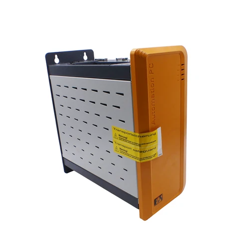
2. Key Technical Specifications
- Brand: B&R Industrial Automation
- Model: 5PC910.SX02-00
- Product Series: Automation PC 910
- Product Type: Two-slot industrial PC system unit
- B&R ID Code: 0xD6DB
- Expansion Architecture: Two PCI slots or one PCI and one PCI Express slot, depending on the installed bus unit
- Interface Options: Two configurable interface-option positions
- CPU Board: Separately installed; compatible CPU-board selection required
- Memory Type: DDR3 SO-DIMM SDRAM
- Maximum Memory: Up to 16 GB, depending on CPU board and configuration
- Storage: One CFast slot and one compact slide-in drive position
- Ethernet: Two shielded RJ45 ports, 10/100/1000 Mbit/s
- USB: Four USB 3.0 ports and one USB 2.0 port
- Serial Interface: One RS232 COM1 port, 9-pin male D-Sub
- Display Interfaces: One DisplayPort and one DVI-I/SDL monitor interface
- Power Supply: 24 VDC ±25%, SELV
- Maximum Nominal Current: 5.5 A
- Maximum Inrush Current: 60 A for less than 300 μs
- Cooling: Passive heat sink, with optional active fan kit
- Protection Rating: IP20
- Real-Time Clock: Battery-backed
- Backup Battery: Renata 950 mAh lithium battery, approximately four-year service life under specified conditions
- Operating Temperature: Depends on installed components and configuration
- Storage Temperature: -20 to +60 °C
- Country of Origin: Not independently verified for the individual unit
- Dimensions and Weight: Refer to the official mechanical drawing and installed configuration
3. Application Scenarios
- Industrial Machine Control: Hosts compatible control applications and machine-level automation software.
- Factory Automation: Supports production monitoring, data collection, and industrial communication.
- HMI and Visualization: Connects to compatible industrial monitors and operator panels.
- CNC and Motion Control: Provides an industrial computing platform for compatible motion-control applications.
- Process Monitoring: Supports data acquisition, equipment supervision, and alarm visualization.
- Industrial Networking: Connects automation equipment through dual Gigabit Ethernet interfaces and optional communication cards.
- System Integration: Supports PCI/PCIe expansion for additional industrial interfaces and specialized hardware.
- Marine and Industrial Equipment: Can be considered for applications where the complete installed configuration meets the relevant environmental and certification requirements.
4. Installation and Commissioning Procedure
- Record the complete model designation, serial number, hardware revision, and installed component configuration.
- Identify the CPU board, RAM capacity, storage device, bus unit, and interface cards.
- Confirm that the available 24 VDC power supply meets the required voltage, current, and inrush specifications.
- Check the installation space, grounding arrangement, cabinet ventilation, and mounting requirements.
- Isolate the power supply and apply the approved lockout/tagout procedure.
- Inspect the housing, connectors, expansion slots, and storage interfaces for damage.
- Install the appropriate bus unit, CPU board, memory, storage, and interface cards according to B&R instructions.
- Connect Ethernet, USB, serial, and monitor cables as required by the application.
- Restore the correct operating system, drivers, and industrial application software.
- Configure BIOS settings, network parameters, system time, and startup behavior.
- Test communication, storage access, display output, expansion cards, and application startup.
- Verify system temperature and stability under normal operating load before returning the machine to production.
5. Configuration and Operating Guidelines
- Select a CPU board specifically supported by the Automation PC 910 system unit.
- Verify the bus unit type before installing PCI or PCIe expansion cards.
- Confirm the memory type, maximum supported capacity, and CPU-board limitations.
- Select compatible CFast or slide-in storage devices.
- Use the correct B&R interface cards for additional CAN, RS232, RS422, RS485, Ethernet, or POWERLINK communication.
- Check monitor and panel compatibility with the installed display interface option.
- Confirm the operating system and B&R Automation Studio hardware support package.
- Maintain adequate cabinet ventilation, particularly when using high-performance CPU boards.
- Back up operating-system images, application files, and system configuration before maintenance.
- Do not assume that two 5PC910.SX02-00 units contain identical CPU, memory, or storage configurations.
6. Daily Maintenance
- Inspect the housing and mounting hardware for damage or looseness.
- Check the power connector and protective earth connection.
- Monitor CPU temperature and system performance.
- Inspect the heat sink and optional fan for dust accumulation.
- Check Ethernet connectors and network communication status.
- Monitor storage health and available disk space.
- Inspect CFast and slide-in drive connections during scheduled maintenance.
- Check the backup battery condition and replace it according to B&R instructions.
- Review system logs for unexpected shutdowns, hardware errors, and communication faults.
- Maintain current backups of the operating system and automation application.
7. Troubleshooting and FAQ
Q1: The Automation PC does not power on.
A: Verify the 24 VDC supply, polarity, protective device, connector, and grounding. Check the power LED and inspect the unit for signs of electrical damage.
Q2: The PC starts but does not boot into the operating system.
A: Check the installed CPU board, BIOS configuration, CFast card, and storage device. Verify that the boot device contains a compatible operating system.
Q3: The display output is unavailable.
A: Check the installed CPU board’s graphics capability, monitor connection, display option, and BIOS settings. Confirm the required DVI-I, SDL, or DisplayPort interface.
Q4: Ethernet communication is unstable.
A: Inspect both RJ45 connections, cables, switch ports, IP configuration, and network diagnostics. Confirm that the installed operating system has the correct network drivers.
Q5: Can the 5PC910.SX02-00 operate without a CPU board?
A: No. The system unit requires a compatible CPU board and the necessary memory and storage configuration to function as a complete industrial computer.
Q6: Can a PCIe card be installed?
A: Yes, depending on the installed bus unit. Supported configurations include two PCI slots, one PCI plus one PCIe slot, or two PCIe x4 slots.
Q7: Can the unit be replaced with a 5PC910.SX01-00?
A: Not automatically. The SX01-00 is a one-slot system unit, whereas the SX02-00 is a two-slot version. Expansion requirements, bus units, and mechanical installation must be checked.
8. Safety Precautions
- Installation and servicing must be performed by qualified industrial electrical and IT personnel.
- Disconnect the 24 VDC supply before installing or removing internal components.
- Follow electrostatic discharge precautions when handling CPU boards, RAM, storage, and interface cards.
- Verify the supply voltage and polarity before connecting power.
- Maintain adequate cabinet ventilation and observe the operating limits of installed components.
- Do not exceed the permitted expansion-card and power-supply specifications.
- Do not remove storage devices while the operating system is accessing them unless the device supports the required hot-swap procedure.
- Protect the system from dust, moisture, and conductive contamination.
- Back up critical application data before changing hardware or software.
- Follow B&R installation documentation and the machine manufacturer’s electrical safety requirements.
9. Related B&R Models and Accessories
The following models and accessories belong to the B&R Automation PC 910 platform and its compatible expansion ecosystem. They are useful for configuration and sourcing reference but are not all direct replacements for the 5PC910.SX02-00.
- 5PC910.SX01-00 – Automation PC 910 one-slot system unit.
- 5PC910.SX03-00 – Automation PC 910 three-slot system unit.
- 5PC910.SX05-00 – Automation PC 910 five-slot system unit.
- 5PC900.TS17-00 – Intel Core i5 CPU board for APC910.
- 5PC900.TS17-01 – Intel Core i3 CPU board for APC910.
- 5PC900.TS17-02 – Intel Celeron CPU board for APC910.
- 5PC900.TS17-03 – Intel Xeon CPU board for APC910.
- 5PC900.TS17-04 – Intel Core i7 CPU board for APC910.
- 5AC901.BX02-00 – APC910 bus unit with two PCI slots.
- 5AC901.BX02-01 – APC910 bus unit with one PCI and one PCI Express x8 slot.
- 5AC901.BX02-02 – APC910 bus unit with two PCI Express x4 slots.
- 5AC901.IETH-00 – Gigabit Ethernet interface card.
- 5AC901.ICAN-01 – CAN interface card.
- 5AC901.I485-00 – RS232/RS422/RS485 interface card.
- 5AC901.HS01-00 – Passive heat sink for APC910.
Check the installed CPU board, bus unit, memory, storage, and interface configuration before selecting accessories or replacement system units.


