
1. Product Description
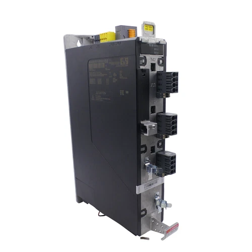
The B&R ACOPOS P3 8EI4X5HWT10.0D00-1 is a three-axis servo drive designed for precise motion control in industrial automation systems. It supports three independent motor connections, each with a continuous output current of 4.5 A, and operates from a three-phase 200–480 VAC supply. The drive integrates digital multi-standard encoder interfaces for motor feedback, electronic protection functions, motor holding-brake connections, and an internal braking resistor. Its compact wall-mounted design supports coordinated motion applications in packaging machinery, machine tools, material handling, and automated production lines. Dynamic node allocation and compatibility with B&R automation engineering environments support integration into configured ACOPOS P3 motion-control systems. The unit is designed for applications requiring coordinated control of multiple servo axes from a single drive module. Before installation, verify the motor specifications, encoder type, braking requirements, power supply, and engineering software compatibility.
2. Key Technical Specifications
- Brand: B&R Industrial Automation
- Product Series: ACOPOS P3
- Model: 8EI4X5HWT10.0D00-1
- Product Type: Three-axis servo drive / servo amplifier
- Mounting: Wall mounting
- Mains Input Voltage: 3 × 200–480 VAC ±10%
- Mains Frequency: 50/60 Hz ±4%
- Continuous Current: 4.5 A RMS per motor connection
- Number of Motor Axes: 3
- Continuous Motor Power: 2 kW per motor connection
- Peak Motor Current: 12.25 A RMS per motor connection
- Peak Output Power: 5 kW
- Maximum Installed Load: 10 kVA
- Nominal Switching Frequency: 5 kHz
- Available Switching Frequencies: 5 / 10 / 20 kHz
- Maximum Output Frequency: 598 Hz
- Encoder Interfaces: 3 digital multi-standard encoder interfaces, EnDat 2.2
- Encoder Communication: RS485, up to 6.25 Mbit/s
- Encoder Cable Length: Up to 100 m, subject to cable configuration
- Motor Holding-Brake Connections: 3
- Holding-Brake Output Current: 1.3 A per connection
- Braking Resistor: Integrated
- Internal Braking Resistor Continuous Power: 150 W
- External Braking Resistor Continuous Power: 2 kW
- Minimum External Braking Resistance: 25 Ω
- DC Bus Capacitance: 470 µF
- Auxiliary Supply: 24 VDC ±25%
- Auxiliary Current Consumption: 1.2 A plus motor holding-brake current
- Protection Rating: IP20
- Dimensions: 374 × 66 × 258.5 mm (H × W × D)
- Weight: Approximately 4 kg
- Operating Temperature: 5 to 40 °C nominal; maximum 55 °C subject to derating
- Relative Humidity: 5–85%, non-condensing
- Software Support: B&R ACP10 V3.12.1 and compatible engineering environments
3. Application Scenarios
- Packaging Machinery: Controls multiple synchronized servo axes for filling, sealing, labeling, and packaging operations.
- CNC Machine Tools: Supports coordinated motion and positioning in compatible machine-control systems.
- Automated Assembly: Provides multi-axis motion control for assembly stations and robotic handling equipment.
- Material Handling: Controls servo-driven transfer mechanisms, conveyors, and positioning systems.
- Printing and Converting: Supports synchronized roller movement and coordinated production processes.
- Industrial Robotics: Provides servo power and feedback processing for compatible multi-axis mechanisms.
- Production Automation: Integrates multiple motor axes into centralized motion-control architectures.
- High-Speed Machinery: Supports applications requiring rapid acceleration, precise positioning, and coordinated motor control.
4. Installation and Commissioning Procedure
- Record the complete drive model, serial number, hardware revision, and nameplate information.
- Confirm the three-phase mains supply is within the specified 200–480 VAC range.
- Verify that each connected motor is compatible with the drive’s continuous and peak current ratings.
- Check the encoder type and confirm compatibility with the installed digital multi-standard encoder interfaces.
- Confirm whether the required connector sets, front cover, and plug-in modules are included.
- Isolate the mains and 24 VDC supply, apply lockout/tagout procedures, and follow the manufacturer’s DC bus discharge instructions.
- Mount the drive vertically in the approved cabinet arrangement and maintain the specified ventilation clearances.
- Connect the mains input, protective earth, motor outputs, encoder cables, and holding-brake connections according to the wiring diagrams.
- Connect the braking resistor arrangement and verify that the selected resistor meets the drive requirements.
- Configure motor data, encoder parameters, axis assignments, and drive settings using the approved B&R engineering software.
- Verify enable inputs, trigger inputs, temperature sensors, and safety-related control signals.
- Perform individual axis tests at low speed before enabling coordinated multi-axis operation.
5. Configuration and Operating Guidelines
- Configure each motor axis independently using the correct motor identification data.
- Match the encoder interface and feedback parameters to each connected motor.
- Confirm the continuous and peak current requirements for all three axes.
- Configure the braking resistor according to the application energy requirements.
- Check the motor holding-brake output wiring and release sequence.
- Use the correct B&R terminal blocks and connector sets for the installed configuration.
- Configure enable and trigger inputs according to the machine control design.
- Verify temperature sensor connections and motor thermal protection.
- Confirm that the engineering software and hardware upgrade package support the installed drive revision.
- Back up drive parameters and axis configurations before modifying the system.
- Observe current derating requirements for elevated ambient temperature, installation altitude, and switching frequency.
6. Daily Maintenance
- Inspect the drive housing for mechanical damage and contamination.
- Check power terminals, motor connectors, and protective earth connections.
- Monitor drive temperature and diagnostic messages.
- Inspect cabinet ventilation and ensure cooling airflow is unobstructed.
- Check encoder cables and feedback connectors for looseness or damage.
- Review motor and drive current values during normal operation.
- Inspect braking resistor wiring and surrounding components for abnormal heating.
- Check the operation of motor holding brakes.
- Review axis synchronization and motion-control alarms.
- Maintain current backups of drive parameters and system configuration files.
7. Troubleshooting and FAQ
Q1: The servo drive does not power on.
A: Check the three-phase input supply, protective devices, 24 VDC auxiliary supply, and wiring connections. Verify the power status and diagnostic indicators.
Q2: One motor axis reports an overcurrent fault.
A: Inspect the motor cable, motor winding condition, mechanical load, acceleration settings, and drive current configuration. Check whether the motor exceeds the permitted current rating.
Q3: The drive reports an encoder communication error.
A: Check the encoder cable, connector pin assignments, feedback supply, and EnDat configuration. Confirm that the encoder is compatible with the installed interface.
Q4: The motor holding brake does not release.
A: Verify the brake wiring, output configuration, supply voltage, and motor brake specifications. Do not apply an assumed voltage to the brake.
Q5: The drive overheats during operation.
A: Check cabinet ventilation, ambient temperature, motor load, switching frequency, and installation altitude. Apply the manufacturer’s derating requirements.
Q6: Can all three motor axes operate simultaneously?
A: The drive is designed for three motor connections. However, simultaneous operation must remain within the permitted current, power, thermal, and braking limits.
Q7: Can an external braking resistor be installed?
A: Yes, the drive supports an external braking resistor arrangement. Observe the specified minimum resistance and power ratings and follow the manufacturer’s wiring instructions.
Q8: Which software is required?
A: The manufacturer’s product data lists ACP10 V3.12.1 support. Confirm the appropriate B&R engineering software and hardware upgrade package for the installed system revision.
8. Safety Precautions
- Installation and commissioning must be performed by qualified industrial drive-system personnel.
- Disconnect and lock out all mains and auxiliary power sources before servicing.
- Follow the manufacturer’s DC bus discharge procedure and verify safe voltage conditions.
- Maintain protective earth and correct cable shielding.
- Never disconnect motor or encoder cables while the drive is energized.
- Observe the specified braking resistor ratings and thermal clearances.
- Ensure that the cabinet provides adequate ventilation.
- Do not bypass enable, protection, or safety-related functions.
- Verify motor compatibility before connecting the drive.
- Perform a complete safety and functional validation after replacement or parameter changes.
9. Related B&R ACOPOS P3 Models and Accessories
The following products belong to the ACOPOS P3 servo-drive platform and associated accessory range. They are provided for identification and sourcing reference and are not all direct replacements for the 8EI4X5HWT10.0D00-1.
- 8EI2X2HWT10.XXXX-1 – ACOPOS P3 three-axis servo drive, 2.2 A per axis.
- 8EI4X5HWT10.XXXX-1 – ACOPOS P3 three-axis servo drive, 4.5 A per axis.
- 8EI8X8HWT10.XXXX-1 – ACOPOS P3 three-axis servo drive, 8.8 A per axis.
- 8EI1X6HWT10.XXXX-1 – ACOPOS P3 single-axis servo drive, 1.6 A class.
- 8EI2X2HWT10.XXXX-1 – ACOPOS P3 drive configuration with 2.2 A continuous current.
- 8EI013HWT10.XXXX-1 – ACOPOS P3 single-axis drive, 13 A class.
- 8EI017HWT10.XXXX-1 – ACOPOS P3 single-axis drive, 17 A class.
- 8EAC0150.001-1 – Digital multi-encoder interface, single interface.
- 8EAC0150.003-1 – Digital multi-encoder interface, three interfaces.
- 8EAC0151.001-1 – Incremental encoder interface, single interface.
- 8EAC0151.003-1 – Incremental encoder interface, three interfaces.
- 8EAD0000.000-1 – ACOPOS P3 LCD display module.
- 8EXA200.0010-00 – ACOPOS P3 orange front cover.
- 8EXF100.0000-00 – ACOPOS P3 replacement fan module.
- 8TB3308.222A-00 – ACOPOS P3 motor connection terminal block.
Check the full order number, continuous current, number of axes, encoder configuration, connector set, braking resistor, and safety options before selecting a replacement or accessory.


