
Product Introduction
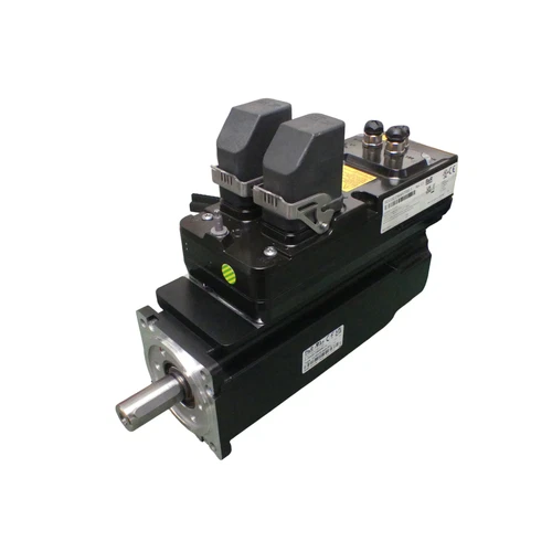
The B&R 8LMA33.D9045CJ00-0 combined with the 8DI330.D90457700-1 is an integrated motor-drive assembly designed for decentralized industrial motion control. The 8LMA motor is paired with an 8DI330 ACOPOSmotor drive, with the inverter electronics mounted directly on the motor housing. This architecture reduces the need for separate cabinet-mounted servo amplifiers and simplifies machine wiring through a hybrid connection system. Published configuration data identifies a three-phase 400 V AC input, an adjustable three-phase output up to 400 V AC, and an output frequency range up to 500 Hz. The assembly is suitable for machine-building applications requiring compact installation, coordinated motor control, and distributed drive architecture. Before installation or replacement, verify the complete motor and drive identification codes, feedback configuration, communication interface, connector arrangement, and machine-controller compatibility.
Technical Parameters
- Brand: B&R (Bernecker + Rainer)
- Motor Model: 8LMA33.D9045CJ00-0
- Integrated Drive Model: 8DI330.D90457700-1
- Product Series: B&R ACOPOSmotor / 8DI Series
- Product Name: Integrated Servo Motor and Drive
- Product Type: Motor-integrated servo drive assembly
- Motor Family: 8LMA
- Drive Family: ACOPOSmotor 8DI
- Drive Size: Size 3
- Input Voltage: 3 × 400 V AC
- Input Current: 0–1.6 A, according to the published exact-combination product reference
- Output Voltage: 3 × 0–400 V AC
- Output Current: 0–2.1 A, according to the published exact-combination product reference
- Output Frequency: 0–500 Hz
- Feedback: Integrated motor position-feedback system; exact sensor execution should be verified from the unit documentation
- Communication: POWERLINK is supported by the ACOPOSmotor platform; confirm the installed interface configuration
- Connection: Hybrid motor-drive connection
- Cooling: Drive electronics cooled through the motor structure, according to the ACOPOSmotor platform design
- Protection Rating: IP65 reported for this exact combination by a distributor; confirm the nameplate and oil-seal execution
- Mounting: Direct machine mounting
- Application: Decentralized servo and motion control
- Certifications: CE and cULus are reported in the product reference; verify the applicable product revision
- Place of Manufacture: Not independently confirmed for this exact unit
- Country of Origin: Seller listing identifies China; verify the individual unit’s nameplate
- Dimensions: Not reliably published for this exact combination
- Weight: Approximately 5.3 kg according to a distributor listing; verify the actual assembly and accessories
- Product Status: Legacy ACOPOSmotor configuration; confirm current manufacturer availability
- Condition: Check the actual listing and seller confirmation for the supplied unit’s condition
- Complete Configuration: Retain both motor and drive part numbers when ordering replacements
Key Technical Features
- Integrated drive architecture: The servo inverter is mounted directly on the motor, reducing the need for a separate motor-drive cabinet installation.
- Decentralized motion control: Supports machine architectures in which drive electronics are installed close to the driven mechanism.
- Reduced wiring requirements: The hybrid connection combines the necessary power and signal connections for the ACOPOSmotor system.
- POWERLINK integration: Supports communication with compatible B&R automation controllers and drive networks.
- Compact machine installation: Helps reduce cabinet space and simplify modular machine construction.
- Motor feedback integration: Uses a built-in position-sensing arrangement for closed-loop motor control.
- Drive electronics cooling: The ACOPOSmotor platform uses the motor structure for cooling the integrated electronics.
- Flexible network topology: B&R documents line and tree topologies for the ACOPOSmotor platform, subject to the system design.
- Industrial protection: The ACOPOSmotor family supports direct machine mounting with IP-rated protection dependent on the exact execution.
Typical Applications
- Packaging and filling machinery
- Automated production lines
- Conveyor and material-handling systems
- Printing and converting equipment
- Industrial assembly machines
- Modular machine-building systems
- Distributed servo motion applications
- Synchronized machine-axis control
Installation Procedure
- Verify both part numbers: 8LMA33.D9045CJ00-0 and 8DI330.D90457700-1.
- Inspect the motor housing, integrated drive enclosure, connectors, shaft, and mounting surfaces.
- Confirm the mechanical mounting dimensions and shaft coupling requirements using the applicable B&R drawings.
- Check the machine’s three-phase supply and protective-device ratings against the drive input specifications.
- Confirm that the required hybrid cable and connector accessories are available.
- Install the assembly in the specified machine position, allowing sufficient clearance for heat dissipation.
- Connect the hybrid cable according to the B&R wiring documentation.
- Connect the POWERLINK network to the compatible controller or network interface.
- Verify protective grounding, cable shielding, connector locking, and network topology.
- Check the motor shaft and driven mechanism for mechanical interference.
- Confirm that the installed motor and drive configuration matches the controller project.
- Complete electrical and mechanical inspection before applying power.
Startup and Power-On
⚠️ Commissioning should be performed by qualified personnel familiar with B&R ACOPOSmotor systems.
- Verify the three-phase supply voltage and protective devices.
- Check the hybrid cable and all power and communication connections.
- Confirm that the motor is securely mounted and the driven mechanism is clear.
- Energize the control and drive system according to the machine startup sequence.
- Check the drive status and diagnostic information.
- Verify POWERLINK communication with the B&R controller.
- Confirm that the controller recognizes the correct motor-drive configuration.
- Check feedback signals and motor identification data.
- Enable the drive only after all machine safety conditions are satisfied.
- Perform a low-speed test movement and verify motor direction.
- Monitor current, torque, temperature, and communication status.
- Increase operating speed and load gradually after successful initial testing.
Normal Operation
During normal operation, the integrated inverter receives motion commands from the machine controller and supplies controlled three-phase power to the motor. The motor feedback system provides position and speed information for closed-loop operation. Communication and motion coordination are handled through the configured B&R automation architecture.
Operators should monitor drive status, communication diagnostics, motor temperature, current, vibration, and mechanical loading. The system must operate within the electrical and thermal limits of the exact motor-drive combination. Ensure that the installation provides adequate heat dissipation and that hybrid cables and connectors remain securely installed.
Parameter Configuration and Modification
- Use the B&R engineering software and documentation compatible with the installed ACOPOSmotor generation.
- Confirm the complete motor and drive order codes before loading configuration data.
- Verify motor identification and feedback settings.
- Configure POWERLINK node identification and network communication parameters.
- Set speed, torque, acceleration, and deceleration limits according to the machine design.
- Check the motor’s rated current and drive output-current limits.
- Configure any applicable brake or safety functions only if the installed hardware supports them.
- Verify controller-axis assignment and motion synchronization.
- Save a backup of the original machine project and drive parameters.
- Do not transfer parameter files from another 8DI330 unit without checking its motor and hardware configuration.
- Perform functional and safety checks after changing drive parameters.
Shutdown Procedure
- Stop the machine through the normal controller sequence.
- Bring the motor and connected mechanism to a safe position.
- Reduce the speed and torque commands to zero.
- Disable the drive through the B&R controller.
- Switch off the relevant power supply according to the machine shutdown procedure.
- Apply lockout/tagout before servicing the assembly.
- Wait for the drive’s internal DC-link energy to discharge according to the manufacturer’s instructions.
- Verify that hazardous voltage is absent before disconnecting the hybrid cable.
- Protect connectors against dust and moisture during storage or maintenance.
Daily Maintenance
- Inspect the integrated drive housing and motor body for physical damage.
- Check the motor shaft and coupling for abnormal movement or wear.
- Inspect hybrid connectors for looseness, contamination, or damaged contacts.
- Check POWERLINK cable routing and connector locking.
- Monitor operating temperature and abnormal heat buildup.
- Check for unusual motor noise or vibration.
- Inspect mounting bolts and mechanical connections.
- Keep the motor surface clean to support heat dissipation.
- Check stored drive alarms and communication diagnostics.
- Inspect cable insulation and protective grounding.
- Follow B&R maintenance instructions for the motor, feedback system, and integrated electronics.
Troubleshooting
1. Motor does not start
- Verify the incoming three-phase supply.
- Check the drive-enable command and machine safety interlocks.
- Review drive status and diagnostic messages.
- Confirm that the controller recognizes the correct ACOPOSmotor configuration.
2. POWERLINK communication failure
- Inspect the hybrid and network cable connections.
- Check the network topology and node configuration.
- Verify controller communication settings.
- Inspect connectors and cable shielding.
- Review the B&R controller and drive diagnostics.
3. Motor feedback error
- Check the integrated feedback configuration.
- Review drive identification and parameter settings.
- Inspect connectors and cable connections.
- Confirm that the controller project matches the installed motor-drive combination.
4. Overcurrent or overload alarm
- Check for mechanical obstruction or excessive load.
- Verify motor and drive ratings.
- Review acceleration and deceleration settings.
- Check for abnormal mechanical friction.
- Confirm that the drive is operating within its specified current limits.
5. Overtemperature alarm
- Check the ambient temperature and installation conditions.
- Inspect the motor surface for accumulated contamination.
- Verify that heat dissipation is not obstructed.
- Review operating load and duty cycle.
- Check for repeated overload conditions.
6. Unexpected motor movement
- Stop the machine immediately.
- Verify axis assignment and direction settings.
- Check feedback and motion-control parameters.
- Review controller commands and safety interlocks.
- Restart only after the cause has been identified and corrected.
Frequently Asked Questions
Q1: What is the B&R 8LMA33.D9045CJ00-0 with 8DI330.D90457700-1?
It is an integrated motor-drive assembly combining an 8LMA motor with a B&R ACOPOSmotor 8DI integrated servo drive.
Q2: Is the inverter installed directly on the motor?
Yes. The ACOPOSmotor architecture integrates the drive electronics into the motor assembly.
Q3: What is the input voltage?
Published product information for this exact combination identifies a three-phase 400 V AC input. Confirm the nameplate before connecting the unit.
Q4: What is the output voltage and frequency range?
The published exact-combination reference identifies an adjustable three-phase output up to 400 V AC and an output frequency range of 0–500 Hz.
Q5: Does this assembly support POWERLINK?
The B&R ACOPOSmotor platform supports POWERLINK communication. Verify the installed configuration and network connection requirements.
Q6: Does the integrated drive require a separate servo amplifier?
The inverter is integrated into the motor assembly, so a separate motor-mounted servo amplifier is not required. The complete machine still needs the appropriate power supply, controller, network, protection, and accessories.
Q7: Can it replace another B&R ACOPOSmotor?
Not automatically. Different 8DI models may have different motor ratings, drive sizes, feedback configurations, connectors, and mechanical dimensions. Compare both part numbers before substitution.
Q8: What should be checked before purchasing?
Verify both identification codes, nameplate ratings, connector condition, motor shaft and mounting dimensions, feedback configuration, communication interface, and available test documentation.
Safety Precautions
⚠️ Electrical Safety: Isolate the three-phase supply and follow lockout/tagout procedures before installation or maintenance.
⚠️ Stored Energy: Allow the internal DC-link capacitors to discharge according to B&R instructions and verify safe voltage before handling electrical connections.
⚠️ Mechanical Safety: Secure the motor and driven mechanism before testing. Unexpected movement can cause injury or equipment damage.
⚠️ Network Safety: Confirm the correct POWERLINK topology and controller configuration before enabling motion.
⚠️ Thermal Safety: Maintain the specified installation clearances and heat-dissipation conditions.
⚠️ Replacement Compatibility: Verify both motor and integrated-drive part numbers. A similar 8DI series designation does not guarantee direct interchangeability.
Related B&R ACOPOSmotor Models and Accessories
The following are related ACOPOSmotor platform references and accessories. Some are family variants or installation accessories rather than complete replacement motors. They are not guaranteed drop-in replacements.
- 8DI330.D90457700-1 – Integrated drive configuration
- 8DI330.ff045hi00-1 – Official ACOPOSmotor size 3 configuration
- 8DI3 – ACOPOSmotor size 3 family
- 8DI4 – ACOPOSmotor size 4 family
- 8DI5 – ACOPOSmotor size 5 family
- 8LMA33.D9045CJ00-0 – Matching motor component
- 8CXC000.0000-00 – ACOPOSmotor size 3 accessory set
- X67AC0M12 – M12 threaded caps
- X67AC0M08 – M8 threaded caps
- ACOPOSmotor hybrid cable accessories – Power and communication connection components
Replacement Note: Only the exact combination and the related platform/accessory references above are included because additional exact part-number variants could not be reliably verified. Before selecting a replacement, compare motor ratings, drive size, feedback configuration, connector arrangement, protection rating, and controller compatibility.


