
The B&R Automation ACOPOS P3 8EI4X5HWT10.0D00-1 is a three-axis servo drive designed for coordinated motion control in industrial automation systems. It supports three independent motor connections, each rated at 2 kW continuous power and 4.5 A continuous current, with a peak current of 12.25 A per axis under specified operating conditions. The unit accepts three-phase 200–480 V AC input and features three digital multi-standard encoder interfaces, integrated braking resistance, motor holding-brake connections, and configurable switching frequencies of 5, 10, or 20 kHz. Its compact wall-mounted design makes it suitable for packaging machinery, machine tools, material handling, and automated production equipment requiring synchronized multi-axis motion. The drive also provides overload, short-circuit, and ground-fault protection. Before installation or replacement, verify the complete type code, connector arrangement, motor and encoder compatibility, DC-bus configuration, braking requirements, and B&R engineering software version.
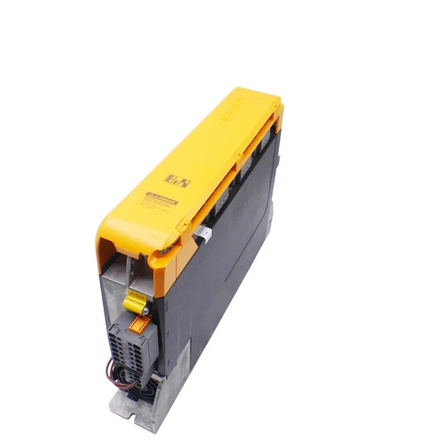
📋 Product Specifications
| Parameter | Description |
|---|---|
| Brand | B&R Automation |
| Model | 8EI4X5HWT10.0D00-1 |
| Product Series | ACOPOS P3 |
| Product Type | Three-Axis Servo Drive / Servo Amplifier |
| Material Number | 8EI4X5HWT10.0D00-1 |
| Axis Configuration | 3 motor axes |
| Mains Input Voltage | 3 × 200–480 V AC ±10% |
| Input Frequency | 50/60 Hz ±4% |
| Maximum Installed Load | 10 kVA |
| Continuous Power per Axis | 2 kW |
| Continuous Current per Axis | 4.5 A RMS |
| Peak Current per Axis | 12.25 A RMS |
| Peak Power Output | 5 kW |
| Nominal Switching Frequency | 5 kHz |
| Available Switching Frequencies | 5 / 10 / 20 kHz |
| Maximum Output Frequency | 598 Hz |
| Control Supply | 24 V DC ±25% |
| Control Supply Current | 1.2 A plus motor holding-brake current |
| Encoder Interfaces | 3 digital multi-standard encoder interfaces |
| Encoder Type | EnDat 2.2 |
| Encoder Signal Transmission | RS485, 6.25 Mbit/s |
| Maximum Encoder Cable Length | 100 m, subject to cable specifications |
| Motor Holding-Brake Outputs | 3 |
| Continuous Brake Output Current | 1.3 A per connection |
| Integrated Braking Resistor | Yes |
| Internal Braking Resistor | 150 W continuous, 7 kW peak |
| External Braking Resistor Capability | 2 kW continuous, 25 kW peak |
| Minimum External Braking Resistance | 25 Ω |
| Mounting | Wall mounting |
| Protection Rating | IP20 |
| Operating Temperature | 5–40°C nominal; maximum 55°C subject to derating |
| Relative Humidity | 5–85%, non-condensing |
| Dimensions | 66 × 374 × 258.5 mm (W × H × D) |
| Weight | 4 kg |
| Place of Manufacture | Not confirmed |
| Country of Origin | Verify product nameplate |
| Product Status | ACOPOS P3 product family |
| Discontinued | Not confirmed |
| Engineering Software | B&R Automation Studio with compatible hardware upgrade; ACP10 V3.12.1 documentation reference |
⚙️ Installation and Operation
- Installation: Disconnect the mains supply and verify DC-bus discharge before installation. Mount the drive in the approved vertical wall-mounted position. Check grounding, mains connections, motor cables, encoder connectors, braking resistor wiring, and cabinet ventilation. Confirm the connector arrangement associated with the exact 0D00 suffix.
- Power-On: Verify the three-phase input voltage and separate 24 V DC control supply. Check motor connections, encoder feedback, holding-brake wiring, and enable circuits before energizing the drive. Observe controller diagnostics during startup.
- Normal Operation: Monitor all three motor axes independently. Check motor current, encoder feedback, drive temperature, braking behavior, and fault messages. Confirm that each axis follows its configured motion profile.
- Parameter Configuration: Use compatible B&R Automation Studio and ACP10 software. Configure motor data, encoder type, switching frequency, axis parameters, current limits, and braking settings according to the connected equipment. Back up the original configuration before making changes.
- Power-Off: Stop all three axes using the approved machine shutdown sequence. Disable the drive, isolate the mains and control supplies as required, and observe the specified DC-bus discharge waiting time before servicing.
🔧 Maintenance and Troubleshooting
- Drive does not enable: Check the mains supply, 24 V DC control supply, enable inputs, and system interlocks.
- Overcurrent fault: Inspect motor cables, motor insulation, mechanical loading, and configured current limits.
- Encoder feedback error: Check encoder wiring, connector seating, feedback configuration, and motor compatibility.
- Overtemperature alarm: Inspect cabinet airflow, mounting orientation, ambient temperature, and installation clearances.
- Braking fault: Check braking resistor wiring, resistance, thermal condition, and configured braking parameters.
- Axis configuration error: Verify the Automation Studio project, ACP10 version, axis assignment, and firmware compatibility.
- Intermittent motor operation: Inspect grounding, cable shielding, connectors, and electrical interference.
🛡️ Safety Precautions
- Installation and commissioning must be performed by qualified industrial drive-system personnel.
- High-voltage AC and DC-bus circuits can retain dangerous electrical energy after power-off.
- Observe the OEM discharge waiting time and verify DC-bus voltage before servicing.
- Never disconnect motor or encoder cables while the drive is energized.
- Confirm motor ratings, encoder compatibility, braking resistor specifications, and cable lengths before commissioning.
- Maintain the specified mounting orientation and cabinet cooling conditions.
- Verify emergency-stop circuits and machine safety functions independently of normal drive control.
- Perform a controlled commissioning test before returning the equipment to production.
🔗 Related B&R Models
The following models belong to related B&R ACOPOS P3 servo-drive families. They are reference models, not guaranteed direct replacements for 8EI4X5HWT10.0D00-1.
- B&R 8EI4X5HWT10.0000-1
- B&R 8EI4X5HWT10.0100-1
- B&R 8EI4X5HWT10.XXXX-1
- B&R 8EI2X2HWT10.XXXX-1
- B&R 8EI8X8HWT10.XXXX-1
- B&R 8EI8X8HWS10.XXXX-1
- B&R 8EI8X8HWT20.XXXX-1
- B&R 8EI8X8HWT30.XXXX-1
- B&R 8EI013HWT10.XXXX-1
- B&R 8EI017HWT10.XXXX-1
- B&R 8EAD0000.000-1
- B&R 8EXF100.0000-00
- B&R 8EXA200.0000-00
- B&R 8EZI8X8HT1.2201-0
- B&R 8EI4X5HWT10.0100-1


